poorren
Junior Member level 3

Hi guys,
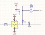
I'm using Mini-Circuit's Gain block amplifier, Gali-4F as receiver's IF amplifier. I used a very simple bias circuit, with a combination with resistor and RF choke. The bias resistor is selected by calculation and experiment. See attachment.
However, the question comes from the bias current change from board to board. I found that when I built the boards with the same resistor, the bias current of Gali-4F will change part by part. Sometimes, the bias current (based on the measure voltage across resistor) could reach 60mA (specification is 50mA). So, I am wondering if this behavior is correct. Or, something of the design is wrong. Based on the mini circuit's datasheet, the operating bias current of Gali-4F should be constant across parts. But, I couldn't conclude that.
So, any replies or answer are welcome, and thanks advance!!
Jeff
I'm using Mini-Circuit's Gain block amplifier, Gali-4F as receiver's IF amplifier. I used a very simple bias circuit, with a combination with resistor and RF choke. The bias resistor is selected by calculation and experiment. See attachment.

However, the question comes from the bias current change from board to board. I found that when I built the boards with the same resistor, the bias current of Gali-4F will change part by part. Sometimes, the bias current (based on the measure voltage across resistor) could reach 60mA (specification is 50mA). So, I am wondering if this behavior is correct. Or, something of the design is wrong. Based on the mini circuit's datasheet, the operating bias current of Gali-4F should be constant across parts. But, I couldn't conclude that.
So, any replies or answer are welcome, and thanks advance!!
Jeff


