Vermes
Advanced Member level 4

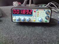
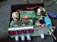
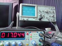
Plates for the generator, frequency meter and noise generator were ordered before.
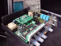
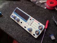
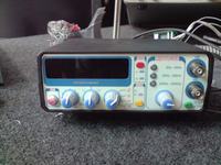
A plate to the generator control and housing were projected then. Some buttons from old amplifiers served as a tool to change ranges. Change of the color means the chosen range of frequency. The keys were taken from the pilot for Unimor. Front panel was drawn in Corel, then printed and laminated. Holes were cut with drill and scissors. After that it was glued with bilateral foil to the plexiglass of 2mm. Previously, a film to the windshields dimming was glued to the plexi. The plate was done in DipTrace.
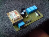
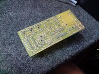
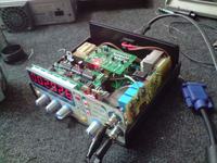
At first, TBA120 noise was planned. Because of it's silent sound and heard changes of the amplitude, the idea changed. The amplitude of the rectangle was reduced to 0,7V. The scheme was never total, it's a conglomeration of different blocks, joined at the process of drawing the plate.
List of things needed:
- plates and kit
- knobs
- housing
- XR
- displays
- chips
- mini isostats
- network transformers
- waveform selection switch

Link to original thread – Generator funkcyjny