Continue to Site

Welcome to EDAboard.com

Welcome to our site! EDAboard.com is an international Electronics Discussion Forum focused on EDA software, circuits, schematics, books, theory, papers, asic, pld, 8051, DSP, Network, RF, Analog Design, PCB, Service Manuals... and a whole lot more! To participate you need to register. Registration is free. Click here to register now.

Fully differential Op-amp with input common mode voltage different from the output

Status
Not open for further replies.

Junus2012

Advanced Member level 5
Joined
Jan 9, 2012
Messages
1,552
Helped
47
Reputation
98
Reaction score
53
Trophy points
1,328
Location
Italy
Activity points
15,235
Hello,

In all the references I read in simulation or measuring the fully differential ampliifer, the setup is set so that input common mode voltage is equal to the output comon mode voltage which set by the value of VCM. For example if I am using single supply operation VDD = 3.3 and VCM is set to the middle = 1.65 V, then I always apply input differential signals for purpose of simulation which are symetrical around 1.65 V,,, Once I tried to change it and the ampliifer fail

I am looking forward for your discussion
Thank you very much

Regards
 

mean for example if I am doing AC simulation gain will be severely degraded, I can say it will not be suitable to work
 

What I can imagine is that if you have for example a resistive feedback around the amplifier and different common-mode voltages for input and output, there has to be a DC current that probably shifts the operating point of the circuit and degrades the gain.
 
The gain won't be degraded unless either input or ouput common mode voltage range or linear output current range are exceeded. Looking at simulation results more closely will tell you what happens exactly.
 
Dear friends,

I also believe that in general, input and output common mode range are indivisuals, the amplifier should work normally as long as they are in range

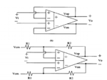
To be more specific, the differential ampliifer I workin on it is not the conventional one, I am working on what so called differentila difference amplifier, it is almost same but this has two differential inputs rather than one, the only text book who talked about it is Gray but in very short at the end of the fully differential chapter,
the transistor level and circuit setup with feedback is shown below

fdd.PNG

ddf2.PNG

Hope you are noe closer to my problem and thank you once again
 

This circuit will most probably require same CMV for the two pairs of differential inputs. Which configuration do you use - the unity gain one or with resistive feedback?
 
This circuit will most probably require same CMV for the two pairs of differential inputs. Which configuration do you use - the unity gain one or with resistive feedback?


Dear Suta,

I hope "This circuit will most probably require same CMV for the two pairs of differential inputs" because I dont have an issue in my design, tested very carefully with different simulation and I chocked when I realized about this issue if it is confirmed that this amplifir needs the same VCM then it means I should balance the sensor bridge to suit this value, and I will be good solutuion,

I have tested for the both configurations

Thank you
 

Basically, it is not a problem if input CM is different than output CM.

The problem with DDA is the DDA itself.
In simple diff-pair, negative feedback keeping inputs equal, while in DDA this statement is no longer true. So, after reaching ≈40mV of input difference, gain is dropped by 10% and for more than 100mV DDA is completely desensitized. In other words, the behavior is like for open loop diff-pair.

Simply, make dc sweep of input voltage amplitude and look for transfer curve (vout vs vin). You will find 3 regions: linear with gain defined by feedback around 0 and two cases with very small gain outside.
 
Basically, it is not a problem if input CM is different than output CM.

Actually my problem is that then input and output must have the same common mode voltage, if I i am using VCM = 1.65 V for the output then the inputs signals must have common mode voltage of 1.65 V. This circuit I want to use it to read differential voltage from the bridge circuit, in which basically I can adjust the common voltage of it by adjusting the resistor ratios, but still I dont know if such solution is accepted in a practical perspective. Specially if we take in to the account that next ADC may require different VCM, then how I will be able to change it

The problem with DDA is the DDA itself.
In simple diff-pair, negative feedback keeping inputs equal, while in DDA this statement is no longer true. So, after reaching ≈40mV of input difference, gain is dropped by 10% and for more than 100mV DDA is completely desensitized. In other words, the behavior is like for open loop diff-pair.

Simply, make dc sweep of input voltage amplitude and look for transfer curve (vout vs vin). You will find 3 regions: linear with gain defined by feedback around 0 and two cases with very small gain outside.

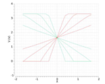
I made this simulation by applying differential input voltage (vin1 increases with X and Vin2 decreases with X) with a different gain setting and common-mode voltage of the input equal to that of the output, results attached below

ddf.PNG

The problem your are talking about it is actually the main problem o DDF that is true, but this usually happens with the traditional connection of the DDf not with the connection above, the traditional connection is the one shown below, here you can see that input transconductance read the differential voltage directly, no feedback is coming on it, thus it will be sensitive to the value of this differential voltage, usually it is no more one overdrive voltage of the input transistor unless if degeneration techniques is employed.
However, with the circuit I presented before, the modification is in the feedback loop to make function in similar fashion of the operational amplifier, thus if you look in to my results, you will see it is accepting wide differential voltage,

ddf3.gif


Thank you very much
 

Status
Not open for further replies.

Part and Inventory Search

Welcome to EDABoard.com

Sponsor

Back
Top