kudjung
Member level 4

Guys,
I've tried to study full bridge inverter for driving the CCFL lamp with a development actual board that I have. Actual board work as expected but the simulation doesn't seem to coorelate well with the actual board.
Here are some of the detail.
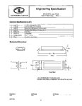
On actual board, There's a single chip CCFL full bridge controller driving 4 Mosfet. The Mosfet then drive the transformer with following manufacturer spec.
Primary Inductance = 210 uH.
Primary leakage inductance = 40 uH.
Secondary Inductance = 1.44H.
Secondary leakage inductance = 290mH.
Turn Ratio(1:82.6)
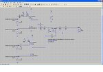
On the simulation, I drive 4 Mosfet with duty cycle and period close to what I've measured on the actual board.
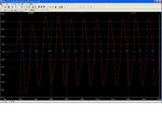
On the actual board I got close to 600 Vrms across 00KOhm load but with the simulation I only get close to 300 V(p-p).
I've attached here the simulation schematic and test result. Also I attached my LTspice simulation file.
Just wondering whether anyone can point out whether I might do anything wrong with this simulation.
Thanks,
KJ


