Vermes
Advanced Member level 4

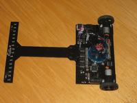
Electronics:
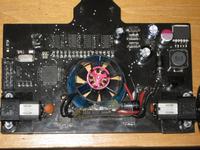
Robot has two microcontrollers. Atmega16 is responsible for read from comparators, calculations of PD regulator and engines settings. Atmega8 supports TSOP and tunnel drive controller, switches LEDs under the robot and sends signals for the „main” processor. Buttons support is also placed on that microcontroller. Atmega16 is clocked by quartz 16MHz, while Atmega8 is powered from internal oscillator 1MHz.
H bridges consist of TB6612FNG.
L7805AC2T are used for stabilizing the logic voltage. LM2576S converter is used for the engines.
Program:
The code was written in C. It is very easy and quick to write. It operates well up to 1,5m/s speed (without the turbine). When the turbine is used, you have to change the coefficients.
Sensors:
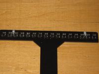
Optocouplers KTIRy0711s were placed in a line. Number of sensors (16) is enough to gain a satisfactory resolution. Analog signal coming out the sensors is given to comparators LM339 and then goes to Atmega16.
PCB:
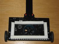
Robot consists of one PCB with black mask. Laminate is 1,5mm thick, because 1mm laminate can break under the action of the turbine.
Engines:
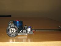
Engines used are Pololu 10:1 in HP version. There are stands made of laminate under each engine. They are painted with black spray.
Tunnel drive:
EDF 27 with recommended regulator 10A. Diodes 3mm protects against too strong bending. Laminate is 1,5mm thick, so it should not break.
Programming:
One 10pin IDC connector in Kanda standard was used for both microprocessors. With help of a jumper, you can determine which processor should be programmed. The jumper sends the signal SCK, what is enough for convenient operation. Also USART is added for Atmega16.
Some videos:
Pictures:
Link to original thread (useful attachment) - Turbinowiec - Robot klasy FTL