Continue to Site

Welcome to EDAboard.com

Welcome to our site! EDAboard.com is an international Electronics Discussion Forum focused on EDA software, circuits, schematics, books, theory, papers, asic, pld, 8051, DSP, Network, RF, Analog Design, PCB, Service Manuals... and a whole lot more! To participate you need to register. Registration is free. Click here to register now.

Frequncy Multiplication/Synthesis Circuit

Status
Not open for further replies.

wfg42438

Member level 3
Member level 3
Joined
Jun 29, 2015
Messages
54
Helped
0
Reputation
0
Reaction score
0
Trophy points
6
Location
California
Activity points
620
Im working on a Warning Speedometer project, im currently having trouble thinking about circuit topologies that can be used for frequency multiplication. Once you do the math (refer to the guidelines below) you see that in order to go from frequency to mph you multiply the frequency of interest by 2.88,this is why i want to design a frequency multiplier. Im thinking i can take the output of this frequency multiplier and feed that into a series of Binary counters (TI 74LS90). Then take the output of the counters to a series of BCD to 7-Segment Decoders (74LS47N) and finally to seven segment displays. Please let me know if there are any topologies i can look into to get this done or if this is even possible. Below is a description of the project and to what devices im limited to, any help would be greatly appreciated.


Design a warning speedometer to measure the speed of an automobile. The input to the system is taken from one spark plug. Each pulse from the plug is 0.5 V in magnitude, and occurs once for each 2 revolutions of the engine. An engine speed of 2500 rev/min results in a speed of 60 mph in high gear. The speed is proportional to the revolutions per minute of the engine assuming that no slippage occurs and that the transmission stays in high gear.

Two outputs are required from the tachometer. These are in the form of a visual display of the speed and an audible tone warning of high speeds.

Three 7 segment LED readouts are to display the speed of the automobile to one decimal point accuracy. An audible tone increases in frequency as the velocity increases above 60 mph. The tone is interrupted at a 10 Hz rate. The frequency of the tone is 500 Hz between 60 and 69.9 mph, 2KHz between 70 and 79.9 mph and 5KHz for speeds above 80 mph.

You must drive an 8 ohm speaker with at least 0.5 watts of power.

This unit must be packaged to withstand the automobile environment and should not exeed 6" x 6" x 2".

The chips and other active devices can only be discrete or TTL / CMOS families.

No microprocessors or other PLA, PAL OR OTHER SUCH SPECIAL DEVICES MAY BE USED. PROMS MAY BE USED IF DRIVEN DISCRETELY.
 

I have not done the math but my first thoughts are why do you want to multiply the frequency? Multiplying by 2.88 would be difficult and require a fractional division PLL.
Why not measure the period between sparks instead? It means the number decreases as the speed increases but that is easier to handle. You can set the scale and resolution of the display by appropriate choice of the clock used to measure the period.

Brian.
 

The reason why I wanted to multiply the frequency is because if i simply read the frequency of the signal applied i will not get the right results. With some calculations you see 2500 rev/min= 60mph where each pulse occurs every two revolutions
....................
Given 2500 rev/min= 60mph
And that one pulse occurs every two revolutions we have:
2500/2=1250 pulses/min
1250/60 sec= 20.83 hz
Therefore 20.83hz=60mph
Which means 20.83hz times x =60 mph so freq times 2.88 =mph
This is why I was considering multiplying the frequency
 
Last edited by a moderator:

Frequency multiplying with an integer factor (and respectively a rational factor M/N) can be done with a PLL, e.g. CD4046 and an external frequency divider. If CD4046 isn't an option, you'll design the PLL from discrete components and digital ICs.

Good luck with your project!
 

I understand the principle you are trying to use and as both FvM and I suggest, you need a PLL to multiply the frequency.

The PLL has to lock to 2.88 times the input frequency, which is difficult, to avoid fractions you have to multiply by 288 then divide by 10. It would be difficult to make a PLL VCO that could cover the entire frequency range from DC (engine stopped) to at least 480KHz (at 80MPH). Even then you would have to measure the resulting frequency, convert it and compare it to see if the speed was > 60MPH.

However, there is another way to do it as I mentioned in post #2.
Generate a fixed clock frequency and use it to drive a counter. Read and reset the counter each time a spark pulse arrives. The figure you read will be proportional to the engine speed without any complicated PLL or VCO. It wont tell you frequency (RPM), it will tell you period (1/RPM) which you can then convert. The other advantage of this method is you can choose the clock frequency to give the resolution (digital point accuracy) you need, in other words enough of your clock pulses between each spark to give the accuracy you want. You can also choose a frequency that makes the RPM->MPH calculation much easier.

It's only a suggestion, you can do it either way but measuring period is the method normally used when the repeat rate is slow.

Brian.
 

Seconded.

Feed the measured repeat rate count to the low bits of an prom address, with a couple of bits of an axillary counter appended to cycle the prom thru 4 different addresses at a few KHz, 4 bits go to a 7 segment decoder to drive the (multiplexed) speed readout, and a couple of bits go to the tone generator controls (7555?).
The problem then degenerates into storing the correct bit patterns into that prom, most easily done by writing a little program in your favourite scripting language to generate the data tables.

While a bit of a pain compared to doing it with a trivial micro, it is entirely doable.

Don't forget that the 'automotive environment' includes some fairly nasty power, and EMI issues, a 7805 or such will not survive a load dump transient.

Regards, Dan.
 

betwixt,
I realize going with the PLL might be too difficult so I'd like to explore the second option you have mentioned. So at this point as the project mentions what is fed into my system is a pulse with a magnified of 0.5v . My initial assumption was to amplify this signal to go from 0 to 5v the acreage logic low and high levels with either a simple amplifier it a Schmitt trigger. As of now I have a Schmitt tigger designed however I might just go with an amplifier circuit as I'll be able to use less components due to the fact my Schmitt trigger needs a diode in order to limit the outputs negative swing in order to approximately go from 800mv to 4.85 v. If you'd like I can post my simulations I have done so you can see what I'm talking about. Now my main concern about this alternative method is I don't quite understand how we're going to measure mph IF were just measuring the period can you please explain how this is being done a bit more? Also how exactly is it were measuring the period with this fixed clock your mentioning?
 

2500RPM = 60 MPH, 1 pulse every two revs, so 1250Hz = 60MPH.

Now lets say full scale is 120MPH (Not something specified), which equals 2500Hz at the input (5000 RPM).

We wish to measure to 0.1MPH, so we need to get at least 20 counts in 1/2500 seconds (Round to nearest threshold should be 0.05MPH), so lets make the count clock say 50KHz.

Now you have a up counter driven by the 50KHz clock, and on the rising edge of the pulse from your schmitt trigger you transfer the count value to a latch and reset the counter.

This count is the number of 1/50000s of a second between one pulse from the ignition and the next.

Now given we don't have a gear input to this thing the lowest displayable speed will be limited by the engine stalling, so you need to go back to your specifier (I am guessing lecturer) and find out what the lowest speed the engine can run at is, as this will define the number of bits of counter you will need in the obvious way.

I would have a retriggerable monostable to inhibit everything when the revs are too low.

The count gives you something related to the speed, so feed it to some of the address inputs of a prom and have it store the data to feed the LEDS as well as the buzzer.

Its actually quite a fun little specification to play with, for all that it is incomplete.

Regards, Dan.
 

Unfortunately 0.5V is below TTL logic threshold and also too low to drive a transistor. I suggest a comparator LM311 or similar will work from a single 5V supply.

The period measurement is the opposite of frequency measurement. To measure frequency you use a known time period and count how many cycles (sparks in your case) occur within the period. For example, if the period was 1 second and 15 pulses occurred within it, the frequency would be 15Hz.

Doing it with period you swap the pulses and period. You create your own pulses (call it the clock) and see how many of them occur between each spark pulse. For example, if you used 1KHz clock and at 60MPH you get 20.83 pulses per second (your calculation in post #3) so between your pulses the counter would have reached 1000/20.83 = 48. If you increased your clock to 10KHZ the count would be 480 and so on, so you can scale the result to fit your calculations. You read the value and then reset the counter at each spark so you get a new count each time a spark pulse arrives.

The advantages are:
no PLL, which I can tell you would be complicated!
you can set the clock frequency to get a good count value at highest engine speed, the value will be bigger at lower speeds.
you can make assumptions such as a huge value means the engine isn't running a all. (Because no pulses arrived to reset the counter)

There is a third method although I wouldn't recommend it and wouldn't get you good marks for the project! You use a long gate time so a lot of pulses can be counted within it. It can be made to give a direct MPH readout but it suffers the serious disadvantage that the display may only update once in several seconds. To measure low speed you may have to wait minutes for the display to change. I doubt that would be accepted.

Brian.
 

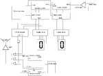
betwixt, s1.PNGs1output.PNG

I feel im starting to understand the use of the clock signal, essentially its a reference in order for us to count the amount of pulses in a single period of the clock signal. Unfortunately im still lost on how exactly this can be implemented. As far as generating the clock signal im thinking i can get that done with a 555 timer in a Astable configuration once i choose what frequency i want it to be it will just come down to choosing two resistors and a capacitor. we need to measure from 0 mph(0 Hz) to 99.9 mph( 34.7 Hz) at this point is where i dont quite understand how this idea works, would please expand some more?
For example if we look at 60mph we have 20.83 pulses/sec, if i want to display 60.0 on the seven segment displays how would i choose the clock frequency to work for this case and at other speeds? I apologize about the numerous questions but im not very familiar with digital logic.

I have also attached the schmitt trigger i was thinking could amplify the input signal. i mentioned earlier. As of know it seems like a good idea however as i mentioned maybe i can just go with a non-inverting OP-Amp configuration to make it simpler.
 
Last edited:

I would not recommend the 741 is used as a comparator, the venerable LM311 is a better choice and only needs a single 5V supply, the same as the other TTL devices you will be using. Connect one input to the 0.5V pulse and the other to a fixed voltage (potential divider) of say 0.3V, it will give a 5V TTL compatible output if you add a pull-up resistor of around 2.2K from the output pin to the 5V rail. In any case, if you used your existing circuit you need an additional resistor at the output of the op-amp to prevent too much current flowing through the diode.

You are starting to understand the principle. Take a step back and think about how you would measure the frequency, you need a known period, we call it the gate period because it works like a perimeter gate, when open things can pass through, when closed the passage is blocked. The gate is opened for the known period and the pulses passing through it are counted, then the gate is closed. The counter will have captured the number of pulses during the period, so if the period was say 1 second, the counter would show 'pulses per second' (=Hz) and you have measured the frequency. Now think about your specific problem, consider the engine is running at 1MPH so using your calculation:

if 60MPH = 2500 RPM then 1MPH = 2500/60 = 41.67 RPM
And that one pulse occurs every two revolutions we have:
41.6/2=20.83 pulses/min
20.83/60 sec = 0.347 pulses per second.

So to measure to 0.1MPH resolution your gate period needs to be at least as long as it takes to count up to 10. That makes the gate period 10/0.347 = about 29 seconds. I'm guessing a speedometer that only updates twice a minute is not acceptable!

Now do it the way I propose and using Dan's suggestion of 50KHz as the reference clock.
The idea is to use the time between the rising edge of one pulse and the rising edge of the next as the gate period. You could equally well use the falling edge as long as you use the same each time. You count the 50KHz clock pulses for the gate period, in other words how many 50KHz pulses occur in the period set by the spark pulses.

Now look at the math:
At 1MPH your spark pulses occur at 0.347 per second so the gate is open for 1/0.347 = 2.88 seconds and the counter receives 50,000 * 2.88 = 144,000 of your reference pulses. Importantly, the update of the speed is 10 times faster than if you had measured the frequency.

At 60MPH, the spark pulses occur at the rate of 20.83 per second so the gate period would be 1/20.83 = 0.048 Seconds and the count would be 50,000 * 0.048 = 2,400 with a display update now 600 times faster than before.

Finaly, at 99.9MPH the pulses occur at the rate of 34.7 per second giving a gate period of 1/34.7 = 0.029 Seconds and a count of 50,000 * 0.029 = 1,450.

The catch is that although you have a number proportional to the speed, it isn't in MPH, in fact the number gets bigger as the speed decreases. Fortunately, that's fairly easy to convert either with some logic gates or easier still with a look-up table. Your project allows you to use PROMS so I would think the simplest, if not most elegant solution would be to use EPROMs (because they can be wiped and re-programmed if you don't get it right first time!). Connect the output of the counter to the address inputs of two 8-bit EPROMS and decode their outputs to directly drive 000 to 999 to the LEDs, you can permanently wire the decimal between the last two digits. You can do it with one EPROM but two is simpler and you also get the benefit of six extra unused outputs which you can dedicate to the over speed alarm if you wish.

In the real World, no engineer in their right mind would do it this way, they would use a simple microcontroller and do everything in software but I guess this is an exercise in finding the optimum methods to solve a problem and not to design something to market.

Brian.
 

Brian and Dan,

Before we move on to the PROM lets take a step back to go over the last post. After reading through the posts i have gathered the following, please correct me if im wrong. The clock frequency is going to be used as a reference clock, we will be counting the number of pulses generated in the allowed time frame. From my understanding wed be counting the amount of 1's or "Logic High" states achieved during the time period we choose. Now it seems our counter receives this clock as the input and will be reset by the 0.5V magnitude pulse being simulated by our function generator. Now say that as Dan mentioned we design a clock of 50kHz and say our current speed is 5mph, this means that we have 1.735 pulses/sec. This also tells us this signal has period of 1/1.735=0.58 seconds, therefore our counter will be allowed to count the amount of pulses in our clock for 0.58 seconds before resetting. Therefore our counter should have the following, at 5mph count=(0.58*50000)=29000 reference pulses counted.

This now brings up the following questions, if the general relationship here is Counter output= (period of clk)*(counted pulses) why not manipulate this right off the bat? Initially we found that to go from Freq->MPH we multiply the frequency of interest by 2.88, however now that i think about it we would need a clock frequency of .347 Hz which is not realistic. Now if this is the relationship we have using our counter how exactly are we to use this to get us closer to measuring the speed of the car? Also it was mentioned that since we need an accuracy of 0.1 mph we need to be able to count up to 10 at least, can you explain why this is the case? Another thing is the relationship for the counter mentioned is under the assumption that we are currently measuring MPH not the incoming frequency why is it that we can assume that? Also if we can go over how we ended up on deciding on using a 50kHz clock, i read the reasoning Dan posted but im still having trouble understanding the reasoning.

I also want to take this post to thank both of you for all of your help so far you guys have been very helpful.
 

It seems they really want to motivate you to learn how to design with PIC with 1973 design constraints.

I would create a master clock to derive all the output results being the lowest common multiple of all resolution , frequency and time constraints.

1. Measure period between pulses, T counting master clock pulses, fc
2. Use result T, to preset divider ratio of another counter of master clock.
3. Measure resulting frequency of fo = f / T in 1sec max with 3 digit decimal resolution using master clock.
4. Convert binary to BCD to 7 segment display x3 digits.
5. Compare most significant digit to derive >=8,7 or 6x
6. MUX audio square waves divided from binary counter of master clock to get 4k, 2k, 500Hz and select according to priority logic from step 5.

For a less complex 2 digit display , consider this;
1. Generate a precision Tach voltage from pulse 1 shot for each 2Rev
2. Use Integrate a Dump method of ADC linear chip and convert to BCD to 7 seg
3. Use 3 speed warning comparators with Relaxation inverter audio tones or proportional squelched VCO
 

Has to be 3 digits with one decimal place resolution Tony so your second proposal is out I'm afraid. You are quite right about the reference clock frequency though, I think Dan chose that as a nice round number but in reality the lowest frequency that allows the required resolution could be used.

This now brings up the following questions, if the general relationship here is Counter output= (period of clk)*(counted pulses) why not manipulate this right off the bat?
That's why I said PROMs are not the most elegant solution but a circuit to calculate the reciprocal of a number could be quite complicated. It's your choice of course. Remember that frequency = 1/Period and frequency is proportional to RPM and hence speed. Using a micro makes it a simple mathematical problem but in hardware it is for challenging.

Also it was mentioned that since we need an accuracy of 0.1 mph we need to be able to count up to 10 at least, can you explain why this is the case?
It really depends on the lowest speed you want to measure. Given the specification calls for 0.1MPH resolution, there must be at least a count of 1 at 0.1MPH or 10 counts per MPH. You can choose a reference clock frequency to achieve that, the frequency is up to you and can be anything you want. Do bear in mind that the count may be out by 1 due to the natural position variation of the reference and spark periods so to minimize that it is better to use a higher than minimum frequency.

Brian.
 

Even if the question demands 10x more resolution than accuracy, the Engineer ought to validate the intelligence of the requirement.

A PLL could perform the required frequency scaling x3600/1250=2.88 with programmable dividers inside /3600 and outside /1250 the loop.

The PLL must have a VCO control range much greater than the typical 4:1 range such as a variable hysteresis relaxation oscillator.

Then with a >1000x clock count required to have the resolution to measure frequency.

The resolution must be validated again for low speeds as being unrealistic to demand 10x more resolution than accuracy possible with source and tire wear affecting gain error. Thus with 3 digit rsolution and 2 digit dynamic range, one would need a master clock 5 decades up with a 100:1 VCO range.

"Sanity Test" ... Don't assume the specs are valid.

But we used to design stuff like this in 1973 , seriously, except 3 digit timers controlled by thumbwheels for programmable delayed record of FM-Seismic and WWVB time signals for Seismic portable cassette recorders in University in 1974, I fixed all the race conditions in the design in 2 dozen units. The geophone cylinders on the concrete floor on max gain could detect my knees flexing across the room on the pavement. It was used for mapping the Earth's crust in arcs down to 30 miles deep after FFT correlation processing on IBM360.

They used 4 tonnes of C4 to raise a smal lake to create the impulse 300km away.

But 0.1 resolution on MPH is irrelevant noise.
===============================
- - - Updated - - -

Using two ratiometric precise clocks and a precision 1 second gate, One can upconvert pulse rate to 10x MPH values using down counters for the pulse interval counting down to measure 1-T, then count down down using external clock to zero in 1 second measuring microsecond counts to display MPH in binary to BCD to 7 seg.

Actual master clock rate to give ratio might be 1250/3600 *10 MHz

5 digit resolution is required for 2 digit speed range and 3 digit resolution thus master clock must be above 1MHz. A 16 bit down counter gives almost 5 digits or 65K.

Two MC14516 8bit counters are cascaded using carry in+out to detect zero. This is easily done with count down enable Muxed between input pulse and master clock for count down intervals.

0.5V Pulse is easily converted to logic levels with ac coupled inverter with 5% hysteresis from second stage inverter for positive feedback with 20M feedback and 0.1second RC time constant with 0.5M negative feedback for self bias from 1st output to make a precision pulse trigger comparator with 2 unused inverters and 2 R's 1C.
 

Brian,

Can we revisit again why the 50kHz clock is the minimum, im still not seeing why its the case? Now establishing that Counter output= (period of clk)*(counted pulses) , how does the PROM fit into getting us closer to measuring mph? I havent used a PROM before so i dont know how they work.
 

If you read my answer , you need 3 digit resolution over a 2 digit range , so your total range is 5 decades higher than your input frequency but that doesn't include scaling ratios.

If using uC logic, easy, compute inverse period, you would only need 3 decades above highest frequency then invert, scale and display.

- to measure 3 significant figures, you must count at least 1000 pulses per cycle.

- but no spec given for min max speed with 0.1 MPH resolution, thus 0.1-99.9 is actual 3 decades not 2 , but not sensible.
 

Can we revisit again why the 50kHz clock is the minimum, im still not seeing why its the case? Now establishing that Counter output= (period of clk)*(counted pulses) , how does the PROM fit into getting us closer to measuring mph? I havent used a PROM before so i dont know how they work.

50KHz was only an example but served to demonstrate that you need a relatively fast count to be able to get enough resolution. Keeping it in perspective, for many applications 50KHz would be considered a snails pace. What you are trying to achieve is a usable number of counts within the 'window' between the start of one spark pulse and the start of the next. If you choose a low frequency, the count will be smaller, fewer of its cycles will pass through the window in a given time. Suppose you used a very low frequency, it would be quite possible that at high engine speeds where the window is short, no cycles pass through and you would get a completely wrong an nonsense measurment. As you increase the frequency, the number of cycles passing through the window for a given speed gets bigger. Your task is to display speed to one decimal place so you must choose a frequency that allows enough cycles to be counted to achieve that. As I said, it doesn't have to be 50KHz, that was just a nice round figure to use in the explanation, you can use a higher frequency than the minimum and get greater accuracy but the minimum is the frequency that allows enough pulses to be counted to get 0.1 resolution in the speed display. If we look at actual figures and assume from the specification that the biggest number you can display is 99.9 MPH the math works out as:

99.9MPH = 34.7 pulses per second = 0.029 Seconds 'window'.
You need to count at least 1 clock pulse in that period or you wont have taken a measurement at all. Given that the count could be +/- 1 anyway, depending on the alignment of the window and your clock pulse edge, it would be far safer to use say 10 times the lowest frequency to make the potential error smaller. Choosing 10 cycles count at 99.9MPH means 10 pulses pass through the window which is 0.029 Seconds wide so the frequency would be 347Hz.

At the other end of the spectrum, the lowest speed you would need to measure is 00.1MPH.
00.1MPH = 0.0347 pulses per second = 29.4 Seconds window.
Counting at the same 347Hz would allow the counter to reach 10,000 which is still a very easy number to work with.

I should point out that in a real life situation, the numbers give to you are somewhat silly because it makes no mention of the gearbox. The spark rate is proportional to engine speed, not road speed and ignoring the gearing means you would be expecting the engine to do less than 10RPM when driving slowly!

Back to the problem - you have a number in the counter which is proportional to the time between sparks. The number in itself is pretty much meaningless because it has no particular units, it's just a value proportional to your chosen clock frequency and inversely proportional to the engine speed. This is where the PROM (or EPROM) comes into play. Your clock frequency should be stable, how exactly you generate it is up to you but it must be assumed to be fairly accurate and consistent. The PROM is just a memory, it has address lines at one side and data lines at the other, when you put an address in, the data at the addressed location comes out on the data lines. In essence, it's a look-up table. So if you know the count value, you can feed it to the PROM address lines and use it to look up the corresponding MPH. From there, it's just a case of displaying it on the LEDs.

The reason I suggested two PROMs is this: You can get PROMS/EPROMs with enough address lines to take all the bits from your counter but the easily available types only have 8-bit data outputs. To simplify the LED display, it would be nice if you had 'easy to decode' 4-bit numbers for each of the three digits, you can then use a TTL driver like the 7447 to interface directly to the segments. That means you can drive two LEDs from one PROM, the third digit from the second PROM and still have four bits left over. That's nice and easy, the bonus is the second part of your task is also made simple. You have to operate an alarm system when the speed exceeds 60MPH and produce different tones as defined limits are exceeded. The PROM is already fed information from the counters about the speed and you have those four bits not being used by the display so why not use one to enable the alarm and the others to control the tone. It removes all the extra checking for the speed completely!

Brian.
 

Status
Not open for further replies.

Part and Inventory Search

Welcome to EDABoard.com

Sponsor

Back
Top