Nurahmed
Junior Member level 1

- Joined
- May 27, 2019
- Messages
- 19
- Helped
- 1
- Reputation
- 2
- Reaction score
- 1
- Trophy points
- 3
- Location
- Montreal, Canada
- Activity points
- 172
Hi,
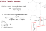
I am designing an LC filter with a cut-off frequency of 20 kHz for the Class-D amplifier. The filter schematic is shown in Fig.1 top right. I understand how to choose the LC values for the critically damped case for the pure resistive load as shown in Fig. 2.
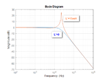
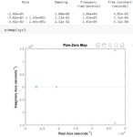
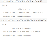
The problem is I want to drive an impedance (400 Ohm + 15 mH) load, where the transfer function becomes a 3rd order, and it has a zero too (Fig.1). The frequency response has a peak for impedance load as shown in Fig.3 & Fig.4. The pole-zero map for impedance load is shown in Fig.5. The transfer function with values for impedance load in MATLAB is also shown in Fig.6.
How can I reduce the quality factor (peak) for this impedance load? How can I find out the quality factor (or damping ratio) for the 3rd order system?
(The problem is the complex poles and the real pole are close together, so I cannot approximate the 3rd order system with the 2nd order system where I can easily write down the damping ratio expression).

Fig.1 LC filter & transfer function

Fig.2 LC values calculation for critically damped filter for resistive load

Fig.3 Frequency response of LC filter with resistive & impedance load

Fig.4 Frequency response of LC filter with resistive & impedance load (LTspice)

Fig.5 Poles & Pole-Zero map

Fig.6 Transfer function of 3rd order filter with values in MATLAB
I am designing an LC filter with a cut-off frequency of 20 kHz for the Class-D amplifier. The filter schematic is shown in Fig.1 top right. I understand how to choose the LC values for the critically damped case for the pure resistive load as shown in Fig. 2.
The problem is I want to drive an impedance (400 Ohm + 15 mH) load, where the transfer function becomes a 3rd order, and it has a zero too (Fig.1). The frequency response has a peak for impedance load as shown in Fig.3 & Fig.4. The pole-zero map for impedance load is shown in Fig.5. The transfer function with values for impedance load in MATLAB is also shown in Fig.6.
How can I reduce the quality factor (peak) for this impedance load? How can I find out the quality factor (or damping ratio) for the 3rd order system?
(The problem is the complex poles and the real pole are close together, so I cannot approximate the 3rd order system with the 2nd order system where I can easily write down the damping ratio expression).

Fig.1 LC filter & transfer function
Fig.2 LC values calculation for critically damped filter for resistive load

Fig.3 Frequency response of LC filter with resistive & impedance load

Fig.4 Frequency response of LC filter with resistive & impedance load (LTspice)

Fig.5 Poles & Pole-Zero map

Fig.6 Transfer function of 3rd order filter with values in MATLAB


