Continue to Site

Welcome to EDAboard.com

Welcome to our site! EDAboard.com is an international Electronics Discussion Forum focused on EDA software, circuits, schematics, books, theory, papers, asic, pld, 8051, DSP, Network, RF, Analog Design, PCB, Service Manuals... and a whole lot more! To participate you need to register. Registration is free. Click here to register now.

Frequency counter 3 Seven segment displays

Status
Not open for further replies.

Rhys Cooper

Newbie level 4
Newbie level 4
Joined
Apr 14, 2015
Messages
5
Helped
0
Reputation
0
Reaction score
0
Trophy points
1
Activity points
40
Hello

Have to design and build a frequency counter for little project. Have a good grasp on the fundamentals but am so stuck on making this. I have made a multisim simulation of what I thought would work after much research, but it doesn't.
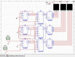
Frequency counter pic.jpg

When I simulate it, the displays don't display anything. If anyone know where I have gone wrong would appreciate the feedback. Or if I am in the totally wrong ball park some guidance would be great!

Many thanks
Rhys
 

The pic of your circuit is too small to be read.
 

I open your image by dragging it to a graphics editor.

Have you tried operating each component by itself, to make sure it works the way you expect? (For instance, can you get any number to appear on one of the displays?)

The columns of IC's must get the correct sequence of gate signals, in the correct polarity. The counter, the latch, the decoder. Not necessarily in that order.
 

Frequency counter pic.jpg

Managed to work out why the displays were not working.

The 74LS47D needed pins 3, 4, 5 connected to vcc +5v.

However now the frequency meter is working with a display, the set frequency on IN A to measure is displayed on the display. But then after another cycle it adds the frequency value on top of the current value so its essentially counting up 450 each time.

Does anyone know how to wire it so that it just keeps the value of the frequency input and only changes if the frequency input changes and changes to the new value?

Many thanks
Rhys
 

managed to get it work a little better by making R01 high, and R92 low. In a hope it would maybe latch and hold the frequency input and then refresh after a set interval which it has.
But I am only getting 99% of the actual number due to the duty cycle of the frequency input which I dont quite understand. So if anyone has any info on this it would be greatly received :)

Frequency display.....kind of working.jpg

Many thanks
Rhys
 

Hi,

you have a gating with a 1Hz frequency and 1% duty cycle --> 99% of 1s is counting. Your measurement window is 990ms.

change frequency to 0.99Hz.
giving 1.0101s * 0.99 = 1.000s

Klaus
 
Thanks, that has sorted that bit out. I was hoping that it work instantaneous, such as if the frequency changed at source the display would show it changed right away. But it takes about 20 seconds for it to then change at the display if I change the input frequency. Is this a wiring problem, or just software related issue?

Many thanks
Rhys
 

HI,

you could start a timing analysis on this.

But most likely it is not "real time" so the delay is from software.

Klaus
 
I think its the software as well so gonna go ahead and build it on a breadboard, and do some real tests on it. Hopefully it works, thanks for all the help everyone :)
 

Status
Not open for further replies.

Part and Inventory Search

Welcome to EDABoard.com

Sponsor

Back
Top