fg
Junior Member level 3

Hi everyone!
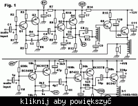
Fig. 1 shows a class A audio amplifier with transformer output. The amplifier in Fig. 2 is much similar to Fig. 1 but it drives headphones rather than a speaker and there is only one emitter follower stage and no interstage transformer, unlike in Fig. 1.
Both circuits show two frequency compensation capacitors (C2 and C6 as in Fig. 1), connected in a similar way. The latter circuit (Fig. 2) has been tested and it does not appear to oscillate except briefly upon startup (don't know why), at an audible frequency (less than 50 hertz).
A brief description of Fig. 1:
Q1 is the error amplifier. Feedback current from the amplifier's output comes to Q1's emitter via resistor R5.
Q2, Q3, and Q4 are voltage amplifier stages. The transformer in Q4's output will raise the stage's output voltage so that it can drive Q5 at a signal level of 12 volts peak-to-peak.
Q5 and Q6 are current amplifiers in common-collector configuration. Q6 drives the output transformer (a 12 ohm to 4 ohm autotransformer). C10 is a bootstrap capacitor, required so as to raise Q5's collector voltage as its base voltage rises.
Resistors R1, R2, R8, R9, R4, and R11 are for biasing the transistors Q1...Q4. R4 will also induce some degree of local feedback from Q2 to Q1.
C5 will prevent local feedback from Q4's collector to Q3's emitter. This allows for a high open-loop gain of the amplifier.
C1 couples the input of the entire amplifier. C4 and C8 are coupling capacitors between the amplifier stages. R13 will provide Q5 with bias current. C9 is intended to keep the bottom of the interstage autotransformer at a constant voltage.
R7, C3, R14, C7, and C11 will provide filtering of supply voltage. They will also isolate the amplifier stages from each other, preventing any kind of undesired feedback via the supply rails.
R3, R6, R10, and R12 are collector load resistors for Q1...Q4, respectively. R15 supplies collector current for Q5.
What I'm concerned about is frequency stability. Will the capacitors C2 & C6 shown in Fig. 1 be enough to prevent oscillation? How many compensation capacitors are required anyway in a circuit like that presented in Fig. 1? Where should the capacitors be located? Are there any formulae for calculating appropriate values for them?
Please ask for any details needed. Any help will be appreciated!

