Vermes
Advanced Member level 4

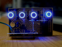
It is an useful device designed while finding a solution how to light a place like hall divided into 4 sections. Few minor cable trays between some of the lamps and on one of them put the radio and/or IR receiver is enough to make this.
The whole could be controlled from few points which were really hard to put the cables.
By the way, an universal 4-channel driver for 230V devices was made. After uploading the appropriate charge, it can be controlled by remote controls RC5, SONY or JVC which have numeric keypads.
To attach CHANNEL_1, press the OK button and then ZERO number on numeric keypad. To put the CHANNEL_1 out, press the OK button and then the number EIGHT on numeric keypad.
CHANNEL_2 – press OK and then ONE – Enable, press OK and then FOUR – Disable
CHANNEL_3 – press OK and then TWO – Enable, press OK and then FIVE – Disable
CHANNEL_4 – press OK and then THREE – Enable, press OK and then SIX – Disable
If turning on or off is not preceded by pressing the OK button on remote control, the channel does not change its state. This was introduced as a security against accidental changeover.
Of course, there is a possibility of making a IR or radio remote control, powered by batteries, like for example:
Pilot IR uniwersalny "inaczej" Olympus,Sony,RC5...
Differently it is with the radio remote control, which after pressing button from 1 to 4 automatically gives sequences as above. There can be few radio remote controls. Everything was closed in housings. Receiver is not seen, with exception of protruding infra red receiver.
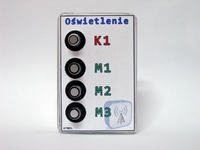
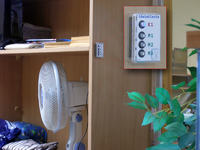
Only the radio remote control was put in the housing(s) with illuminated keys. Of course, this illumination eliminates the battery power. In assumptions, the remote control can be hung in any place and only the supply voltage from 7V to 12V has to be led. Power consumption is very low.
When the channels are out, the keys are illuminated. When the channels are on, keys gently blink from time to time.
The whole works well in version with RF 433MHz control.
If it is for radio, TELECONTROLLI sets were used:
- Telecontrolli-Transmitter-RTFQ2-433MHz-R
- Telecontrolli-Receiver-RRFQ1-433MHz
- Aurel-Transmitter-fm-mid
- Aurel-Receiver-rx-4m50fm60sf
Nad/Odb 433MHz - kod Manchester - porównania/ranking
Range of trouble-free operation is 150-200m and in the open 300-400m.
Remote control:
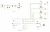
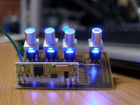
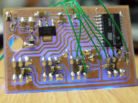
Receiver:
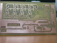
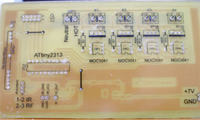
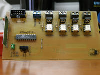
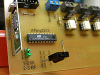
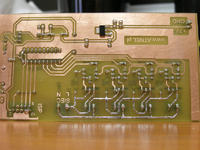
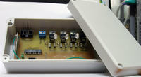
Housing of the receiver:
Housing of the remote control:
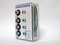
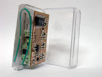
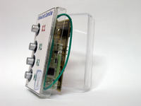
Live in action:
Plates were lacquered on both sides. That is why the description of elements on top is visible, on bottom side there is copper protected against rust. Additionally, lacquer does not interfere if you want to solder anything. Lacquer is in the picture below:

Software was written in C, Eclipse environment.
Jumper on the receiver is to switch if you want to receive the IR remote or 433MHz radio remote control.
Link to original thread (videos and attachments) – Czterokanałowy sterownik IR lub RF(433MHz) - 230V