Continue to Site

Welcome to EDAboard.com

Welcome to our site! EDAboard.com is an international Electronics Discussion Forum focused on EDA software, circuits, schematics, books, theory, papers, asic, pld, 8051, DSP, Network, RF, Analog Design, PCB, Service Manuals... and a whole lot more! To participate you need to register. Registration is free. Click here to register now.

Force variation with increasing/decreasing distance and angle?

Status
Not open for further replies.

Naveed Ahmed

Member level 4
Member level 4
Joined
Aug 31, 2008
Messages
77
Helped
9
Reputation
18
Reaction score
9
Trophy points
1,288
Location
Singapore
Activity points
1,862
Practicle/Real Setup:
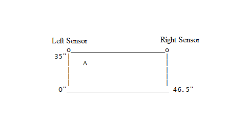
I have a glass screen of length 35" and width 46.5". I have mounted one force sensor at the left
top of glass screen and another sensor on the right top of the glass screen. Now, if I press my glass
screen from any point on the screen I shall get some force at the left and some force at the right sensor output accordingly.


o_______________________o
35"| |
| A |
| |
| |
| |
0"_________________________ 46.5"

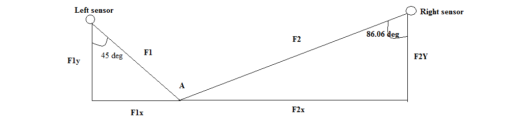
I have hard and tought time to solve this problem. I pressed at point A with (x,y) = (3,32). At the left sensor I am
getting 7.015 Newtons. How much force I shall expect/get at right sensor?? Please refer the below info as well.

Point A with left sensor:
Angle = 45 degrees
Distance from sensor = 4.24"

Point B with right sensor:
Angle = 86.06 degrees
Distance from sensor = 43.6"

You can calculate angle and distance with your own calculation if I am wrong.

Thanks alot in advance,

Best Regards,
Naveed

---------- Post added at 08:33 ---------- Previous post was at 08:26 ----------

90_1312097568.png


Sending image for your reference.

Thx
 

Glass plate, did not rest on just a 2 points
Support points must be at least 3 or more

Before you can calculate the distribution of forces and directions
You need to know all the support points against the power

Plate_Forces_01.jpg

Regards KAK
 
Last edited:

Thx KAK,

Can you explain why do I need more than 2 points plz? My application can only have 2 points measurement. Actually I have to calibrate the right sensor with respect to value given by left sensor. I am taking left sensor as a reference value and will calibrate the right sensor accordingly.

Best Regards,

Naveed

---------- Post added at 10:49 ---------- Previous post was at 10:13 ----------

Dear KAK,


The calculation which I did is as follow:

At left sensor:
F1 = 7.01 N (given)
angle = 45 degree.
F1x = F1 * sin(angle) = 7.01 * sin(45) = 4.95 N
F1y = F1 * cos(angle) = 7.01 * cos(45) = 4.95 N

At right sensor:
angle = 86.06
As F1Y = F2Y , if magnitude and direction are same then force vector is also same.
F2 = F2Y/cos(angle) = 72 N

Why F2 is so high, it was expected lower than F1. I think we need to consider distance as force is decreased by increasing the distance.

Naveed
 

It is true, that measuring can be done with one sensor, when you calibrate the needed measure range.

Method used when you calculated : Right sensor value should be near >> (left sensor) * (line F1) / (line F2)

Before you can calculate any force vector, you must realize and calculate
all the force vectors simultaneously and together.

You have to know, where the force generated by you is transferred to the plate surface,
and how it is divided to the external support points and the sensors.

I take an example:

If plate is supported like window screen, your added force is divided to all directions.
because of an infinite number of the support points are located in the edges of the screen.

Minimum number of the supports needed to put screen on table is 3.
2 sensors and 1 additional point.

Can you show me , how is the screen is (fixed ) supported, it can´t float in the space.

Or it is window like this....

Screen_fix.jpg

KAK
 
Last edited:

Dear KAK,

So do I need more than two sensors? Or I need something else. My screen is fixed in the lab and I am at home right now, I will send you the picture of glass screen. Actually, the sensors are mounted at the back side corner of glass screen, so if screen is pushed from any point it will press the sensors and we can find the force accordingly.

When I push the screen from distance "d" to left sensor it gives me some value and when I push the sceen from distance "d" to right sensor then I get some other value. I expect the same values when the distance is same. Thats y I want to calibrate, I want to take one point(Sensor) as a reference so I want to find out the other sensor's expected value so that I can calibrate other sensor accordingly.

Thanx,

Regards,
Naveed
 

Hi,

If there were exactly 3 points of support, the system is statically determinate (isostatic) and it can be solved by the 3 conditions of equilibrium.
Suppose the 3 supports are the ponts UL and UR (upper left and right corners) and LL (lower left corner). Choosing (arbitrarily but for simplicity) the point UL as reference for the moments, the contitions can be stated as follows:

a) sum of all forces in z-axis is 0
b) sum of all moments in x-axis about point UL is 0
c) sum of all moments in y-axis about point UL is 0
In this way, the 3 unknown forces (force at A, and reactions at UR and LL) are found.

If the third support were the point LR (lower right corner) instead of LL, the solution would be different.
Now, if there are more that 3 supports, the system is statically indeterminate (hyperstatic) and the reactions depend of the elasticity of the plate and the number and locations of the supports.
Are there supports in LL AND LR? All the lower side is supported? etc...

Regards

Z
 

Hi Zorro,

thanx alot for this,

LL and LR are not supported. We only have UR and UL right now. And we dont want exact UR force to find, we just want to find the estimated/expected UR value by taking UL value as a reference. We need to drive one relation for calculation of UR using UL.

We have UL which is known , UL = 7.01N. I can also read UR which is 0.22N but thats wrong thats why I want to calibrate UR by taking UL value as a reference.

Naveed
 

What do you mean by lower side supported?

I mean we only have two sensor points that are UL and UR. At the lower side there are no sensors mounted!
 

You read two values ​​(ie 0.22N 7.01N and), but as you do not know the applied force, you have only as data the relationship: u = UR/UL = 0.22/7.01

It is obvious that one fact you can not know the coordinates [x, y], just think that the pressure at any point in the vertical median line between the sensors always give UL = UR
More general, every value of u = UR/UL corresponds to a curve on the plate, not to a point.

--> You need at least 3 sensors.
 

What do you mean by lower side supported?
I mean we only have two sensor points that are UL and UR. At the lower side there are no sensors mounted!
I mean that equilibrium requires at least three points supported (no need of sensors).
Supports at UL and UR poins are not enough. The plate would rotate around the upper side line when you apply a force!
Regards

Z
 

Status
Not open for further replies.

Part and Inventory Search

Welcome to EDABoard.com

Sponsor

Back
Top