wjxcom
Full Member level 5

Dear all,
I need your advice on designing the taps of the compensation FIR filter for a sigma-delta ADC that uses an FIR DAC.
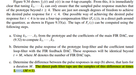
Please refer to the attached figure, which is taken from the second edition of "Understanding Delta-Sigma Data Converters" (page 291). From the figure, it can be seen that the author completes the design of the compensation FIR in three steps: a, b, and c.
My question is, the compensation FIR should also have M taps. However, the book states: "The direct path filter taps are the samples of this difference at times 1, ..., (M-1)," which would only result in M- taps! How should the remaining tap be determined?
I would appreciate any guidance on this, thanx!
I eagerly await your replies!!! Thanx!!!
