Vermes
Advanced Member level 4

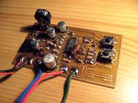
The scheme can be found at **broken link removed**.
This project was inspired by simple radios with two buttons. SCAN finds the next station, and RESET returns to the start of the range. The main element of this type receivers is TDA7088T chip or CD9088CB. They are ASIC highly integrated systems, which are connected to only what could not be integrated on the silicon structure, e.g. larger capacitors, coils and the capacitance diode.

There was no problem with capacitors. Coils were counted and wound manually, because of non-typical values used: 70nH and 78nH. Inductance meter may be useful. Incorrect coils cause incomplete coverage 88-108MHz range. It is worth remembering that stretching the coil reduces its inductance, and the compression or insertion of a metal core inside the coil increases the inductance.
The capacitance diode is used for automatic tuning. The potentiometer has to be a logarithmic one to make tuning easier.
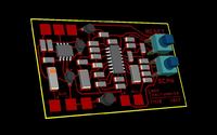
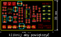
The whole is made on SMD elements and soldered using heating plate. This method is perfect for this purpose, because elements solder in a moment.
Antenna should have length of half a wavelength. In practice, radio received some stations with a piece of wire.
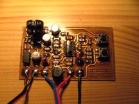
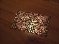
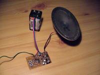
The system is powered by 3V max 5V and consumes approximately 10mA. Radio's size is similar to a box of matches.
Link to original thread (useful attachment) – **broken link removed**