Continue to Site

Welcome to EDAboard.com

Welcome to our site! EDAboard.com is an international Electronics Discussion Forum focused on EDA software, circuits, schematics, books, theory, papers, asic, pld, 8051, DSP, Network, RF, Analog Design, PCB, Service Manuals... and a whole lot more! To participate you need to register. Registration is free. Click here to register now.

FM modulation and Demodulation circuit

Status
Not open for further replies.

Elizabeth Carli

Newbie level 4
Newbie level 4
Joined
Mar 18, 2014
Messages
5
Helped
0
Reputation
0
Reaction score
0
Trophy points
1
Activity points
41
Suggest FM modulation and Demodulation circuit with external Fc
 

A Varicap is a variable capacitance diode where the amount of its reverse voltage determines its capacitance. When it is parallel with an inductor then the LC in an oscillator can be an FM modulator. A simple transistor can also be used as a varicap and the transistor is the oscillator.

You can find FM demodulator circuits in Google. The latest cheap radios use a quadrature detector and hifi circuits use a ratio detector or discriminator.
 

Suggest FM modulation and Demodulation circuit with external Fc


Hi Elizabeth
Your Question isn't clear . you simply have asked for FM mod and demod circuits . for whay kind of specifications ? for how much precision ? or ....?
For general purpose you can have a look into CXA sries of integrated circuits which are FM detectors . or PLL discriminators . or have a search for coincidence detectors in google . or .....
There are many kind of detectors for FM . ( foster seely / travis/ PLL / stable circuits / slope / coincidence/ quadrature / ..... )
And the same is applied for modulators . tell me your application then i can lead you through the best way .
Best Wishes
Goldsmith
 

i want a simple FM modulator and demodulator circuit with Fc=250kHz using 555 timer ic. Im unable to find working circuits on google.
- - - Updated - - -

I want a simple FM modulator and demodulator circuit with Fc=250kHz using 555 timer ic or without any IC. Im unable to find working circuits on google.
 

Why do you want to use a 555 timer to produce FM? FM requires a voltage-controlled oscillator where audio frequencies vary the frequency of the carrier and the levels of the audio vary how much the frequency varies. A 555 does not have its frequency varied by voltage.

Why do you want to use a 555 timer to demodulate FM? An FM detector needs to produce an output voltage depending on changes of a frequency. A 555 does not DOO DAT.

I think some wireless headphones use an Fc of about 250kHz that has infrared modulated with FM. Their circuit is not simple.
 

I think if you wired a 555 up as an astable, feeding audio into the "charge" resistor would alter the pulse width, so would perform a crude form of FM.

" circuit with external Fc", you use an IF system at least that is what professionals do. Choose an IF frequency, then use a reference crystal oscillator, so that the Nth harmonic of it and the N+1 harmonic are equidistance in frequency from your IF. So for 250 KHZ, use a 100 KHZ reference, then select the 200 KHZ and 300 KHZ. Now FM your If oscillator and use two frequency comparators and low pass filters, to get a DC out to stabilize the centre frequency. Mix the FM IF output up to your wanted carrier frequency if required.
Frank
 

i want a simple FM modulator and demodulator circuit with Fc=250kHz using 555 timer ic. Im unable to find working circuits on google.

Hi Elizabeth
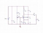
Okay , i'll guide you more . i've designed this circuit for you . first try to build it and see if there is any oscillations at 250 KHZ . i hope you have oscilloscope to see the wave shape . if you have no access to the oscilloscope tel me to give you another circuit just to understand about the out put wave .

after that i'll tell you how to inject your message signal to make it FM modulated . and then i'l lead you through the receiver .
Here the circuit comes :
FM.JPG
The out put will be appear across the 100k ohm resistor .
Try to vary the potentiometer while you see the oscillation at the out let .
Best Wishes
Goldsmith
 

I don't see what's wrong with using a 555 at 250KHZ. Personally I wouldn't because of it's stability but it's quite feasible to do it. I think people are immediately thinking FM means audio when in reality it can be anything from FSK to disk data recording to video.

Brian.
 

I don't see what's wrong with using a 555 at 250KHZ. Personally I wouldn't because of it's stability but it's quite feasible to do it. I think people are immediately thinking FM means audio when in reality it can be anything from FSK to disk data recording to video.

Brian.
Hi Brian
I think when i've asked about the details she told that she want a simple FM modulator and nothing else ( like FSK or ... ) isn't it ? however 555 deals with some unwanted harmonics that must be filtered as well and of course the our put for 555 is dealing with DC component which must be decoupled . but what i've presented is just a sine wave oscillator . isn't it ? so i guess it must be better . :wink:

Regards
Goldsmith
 

I see an oscillator but I do not see how changing the tiny capacitance of the transistor with a modulation signal will create useable FM.
This oscillator is usually used at 100MHz which is 400 times higher then the frequency swing is useable.
 

I see an oscillator but I do not see how changing the tiny capacitance of the transistor with a modulation signal will create useable FM.
This oscillator is usually used at 100MHz which is 400 times higher then the frequency swing is useable.

Hi Audioguru
I suppose that you know how to use a cap multiplier ? and i guess that you know how to use varicap diodes . right ? thus , with adding some simple changes in that circuit , that is truly possible .

Regards
Goldsmith
 

Hi Audioguru
I suppose that you know how to use a cap multiplier ? and i guess that you know how to use varicap diodes . right ? thus , with adding some simple changes in that circuit , that is truly possible.
It is a 250khz oscillator. Its tuning and feedback capacitors are 1000 times the tiny capacitance of the transistor so FM at this low frequency will not work that way.

EDIT: The tuning and feedback capacitors are one BILLION times (not one thousand times) the tiny variable capacitance of the transistor.
 
Last edited:

It is a 250khz oscillator. Its tuning and feedback capacitors are 1000 times the tiny capacitance of the transistor so FM at this low frequency will not work that way.

EDIT: The tuning and feedback capacitors are one BILLION times (not one thousand times) the tiny variable capacitance of the transistor.
Hi again
Of course it will work ! just using some capacitive diodes in parallel and adding the message signal to the emitter much be better . the modulation ration in this situation is low but with using some capacitive diodes in parallel and adding the message signal to the emitter it will work with acceptable modulating ratio . don't you wanna have a test on it ? trust me !

Best Luck
Goldsmith
 

I wonder where he will find an FM radio that operates at only 250kHz and with an FM deviation of almost nothing?
 

I wonder where he will find an FM radio that operates at only 250kHz and with an FM deviation of almost nothing?
About 5 years ago , i built an FM modulator at 500 KHZ without any kind of capacitive diode and only with adding the source signal , to the emitter of the circuit which i've mentioned , variations of frequency were as good as i could see them with my oscilloscope as well . so 250KHZ is about half . it will work too , and if we add the capacitive diode it will work much better too .

Best Wishes
Goldsmith
 

The FM receiver is easy, just use the signal as the input to a diode pump, it will produce the modulation. That circuit is very poor, if you insist on using Goldsmiths circuit, you must replace part of the tuned circuit capacitance with a miller effect transistor, that is a transistor biased, so the the modulation changes the GAIN of the transistor. This is done by running the transistor at a very low current and connecting a capacitor between the collector and base. Looking in at the collector the capacitance seen is this value times the gain of the transistor.
There is NBFM, narrow band FM, where the deviation does not exceed 5 KHZ.
Frank
 
hi, i am new here working on a similar project on FM modulator circuit and demodulator circuit.
do you happen to have any source of designing a simple demodulator circuit? It doesn't matter which demodulator type as long as is simple enough. the budget granted by my uni was too little for complex circuit tq :)
 

Status
Not open for further replies.

Part and Inventory Search

Welcome to EDABoard.com

Sponsor

Back
Top