kingtal0n
Junior Member level 3

Hello, I am new to electronics and trying some things,
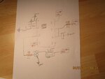
This is my first attempt at using a 555 timer.
I need some help to make sure it is safe to use and will work the way intended.

The circuit seems to work fine:
1. when power is applied (12v car battery) the LED lights up to show circuit is energized and waiting for switch to close
2. when switch (pin2: trigger) is pulled to ground, the 555 turns ON the relay for a few seconds (and the LED turns OFF), then flips it back off and waits for the process to repeat
I plan to use this in a car as a security measure to disable the neutral safety switch. I plan to put a switch on the input VCC so I can also hide that as well. I have a ton of questions though:
1. how much power will the circuit draw if I happen to leave it on, can I make it use less power, so that I can leave it energized ALL the time?
2. is it safe to directly ground pin 2 or do I need a resistor there, it works fine with a resistor doesn't seem to care
3. Should I put a capacitor on pin5 and pull it to VCC like so many diagrams have?
4. Are the resistors big enough? I have a 1k on the transistor and 120k on "discharge" not even sure if I used it properly
5. I noticed that without the capacitor C1 against ground for pin2, the 555 will auto-trigger when powering up. I don't know why this capacitor keeps it from auto-firing and I am not sure how large of a cap to use here, I just stumbled on this fix.
6. Is the transistor 2N4401 the right 'size' for typical 30-50 amp automotive relay coils? Its just what I happened to have
7. It seems strange there is no resistor anywhere inline for the transistor to relay circuit. yet many diagrams online do not have them. I don't know how to tell when its safe to leave the resistor out.
This is my first attempt at using a 555 timer.
I need some help to make sure it is safe to use and will work the way intended.

The circuit seems to work fine:
1. when power is applied (12v car battery) the LED lights up to show circuit is energized and waiting for switch to close
2. when switch (pin2: trigger) is pulled to ground, the 555 turns ON the relay for a few seconds (and the LED turns OFF), then flips it back off and waits for the process to repeat
I plan to use this in a car as a security measure to disable the neutral safety switch. I plan to put a switch on the input VCC so I can also hide that as well. I have a ton of questions though:
1. how much power will the circuit draw if I happen to leave it on, can I make it use less power, so that I can leave it energized ALL the time?
2. is it safe to directly ground pin 2 or do I need a resistor there, it works fine with a resistor doesn't seem to care
3. Should I put a capacitor on pin5 and pull it to VCC like so many diagrams have?
4. Are the resistors big enough? I have a 1k on the transistor and 120k on "discharge" not even sure if I used it properly
5. I noticed that without the capacitor C1 against ground for pin2, the 555 will auto-trigger when powering up. I don't know why this capacitor keeps it from auto-firing and I am not sure how large of a cap to use here, I just stumbled on this fix.
6. Is the transistor 2N4401 the right 'size' for typical 30-50 amp automotive relay coils? Its just what I happened to have
7. It seems strange there is no resistor anywhere inline for the transistor to relay circuit. yet many diagrams online do not have them. I don't know how to tell when its safe to leave the resistor out.


