Continue to Site

Welcome to EDAboard.com

Welcome to our site! EDAboard.com is an international Electronics Discussion Forum focused on EDA software, circuits, schematics, books, theory, papers, asic, pld, 8051, DSP, Network, RF, Analog Design, PCB, Service Manuals... and a whole lot more! To participate you need to register. Registration is free. Click here to register now.

Finding time constant of switched capacitor circuit

vug

Newbie
Newbie level 3
Joined
Jul 4, 2024
Messages
4
Helped
0
Reputation
0
Reaction score
0
Trophy points
1
Activity points
37
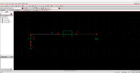
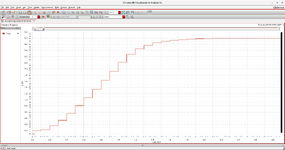
In the simulation output of this switched capacitor charge pump (attached below) , how to find the time constant?
Should the find the circuit time constant or is there time constant for each step in the transient?

Please help me with it. (I simulated the circuit in discrete z domain).

voltdoub.jpg
 
You can figure a time constant for any care-about.
But first you must declare what is the basis. From
what, to what end result?

Expect the CP will vary its time-to-final-value (and the
value itself) widely with load. So must wrap some
conditions around it too.
 
There's a handy rule about determining RC time constant: Set all voltage sources to zero, then calculate how long it takes the capacitor to drop 63% amplitude, through any and all resistors which influence it. Standard definition of RC time constant.

We don't need to count time that the switch is off (that is, very high resistance). We only need count time that the capacitor spends changing volt level. Clearly switching duty cycle is a chief factor. The net effect is to create average resistance which we can consider in the RC time constant. Duty cycle for charging is not necessarily the same as for discharging.

The duty cycle for charging can use the same approach, since we're looking at the 63% change in amplitude as before, and timing how long it takes.
 
There's a handy rule about determining RC time constant:
RC time constants hhave an 1/exponential shape.

But in the given graph (large scale), one can see linear shape.
For sure one can apply the 63% rule here, but the resualt is not the same. Still it is a vaid measure.

@OP:
since there are two "time constants", you need to decide which one you are interested in.

Klaus
 
The linear ramp suggests current limited operation, e.g. switch transistors in saturation, respectively circuit behavior it can't be appropriately described by a time constant.
Furthermore time discrete circuit behaviour is ruled by the combination of linear circuit properties and sampling frequency. Time constant applies to linear circuits only.
 
From chatgpt :

Basically effective tau = RC / T (sample data time)


Entire chat attached.

Note RC/T is dimensionless, further chat dialog conveys this effective time constant is a reflection
of system dynamics..... not exactly precise but physical interpretation of ratio seems right.


Regards, Dana.
 

Attachments

  • I have a RC circuit.zip
    19.4 KB · Views: 34
Last edited:
Series parallel Charge pump

`include "constants.vams"
`include "disciplines.vams"

module singlecpdis (in, out);
inout in,out;
electrical in, out;
parameter real n=2;
parameter real CL = 100e-12 from (0:inf); // Capacitance C
parameter real C = 100e-12 from (0:inf);
parameter real T = 1e-7; // Sampling period
analog begin
V(out)<+zi_nd(V(in),{1,n},{1+(n*CL/C),-(n*CL/C)},T);
end
endmodule

This is the code and schematic i am working on, this is a 2 stage switched capacitor charge pump. Now , i have to find the time constant of each step. And it is found in the previous research paper that equalization time constant is 1/6 th of the semiperiod. But i doesnt go well with what i did. kindly guide me.
 

Attachments

  • schemserparn2.png
    schemserparn2.png
    85.8 KB · Views: 52
  • serparn2.png
    serparn2.png
    100.9 KB · Views: 40
What "time-constant" are you referring to?
Is it the time it takes the charge-pump to reach it's final voltage value?

Show the circuit schematic.
Time constant of a sampled V source feeding a RC series network. As stated by OP in post # 1.
 
There is a rise time, dt for each clocked step which is smaller than the display resolution.

Then there is a settling time after the input remains constant, which depends on the cascaded stages of the charge pump.

It looks like this was a no-load test as the output is exactly 2x Vin.

1721854084245.jpeg
 
@crutschow

I did not see that stated in post #1.

OP questions time constant for a charge pump, sims it in Z domain without parasitic consideration,
as near as one can tell from his post, namely R, in actual practice a RC circuit more appropriate, I
assumed L was negligible. So effort was being made to show Op a more general case. So some
observers may not see that interpretation from OP original post but more general case pertinent.
Clearly I should take more time to explain the interpretation for all forum supporters.

I also prefer that the TS answer my question as that's who it was directed to.

Given no "@OP" in your post #7 one cannot read minds it was only for OP, and not other
posters discussing the basic question. My apologies for responding to your post immediately
following my post #6, clearly a violation of posting protocol. Maybe we should all use @NOONEBUTOP
or @ONLYOP when targeting OP......
 

LaTeX Commands Quick-Menu:

Similar threads

Part and Inventory Search

Welcome to EDABoard.com

Sponsor

Back
Top