Continue to Site

Welcome to EDAboard.com

Welcome to our site! EDAboard.com is an international Electronics Discussion Forum focused on EDA software, circuits, schematics, books, theory, papers, asic, pld, 8051, DSP, Network, RF, Analog Design, PCB, Service Manuals... and a whole lot more! To participate you need to register. Registration is free. Click here to register now.

Filtering noise from power supply with one Inductor.

Status
Not open for further replies.

giovaniluigi

Member level 1
Member level 1
Joined
May 30, 2009
Messages
32
Helped
0
Reputation
0
Reaction score
0
Trophy points
1,286
Activity points
1,626
I have a circuit that needs a 12V power line and for that I built a DC-DC converter with 12V output (5A).
This 12V line is used to power a small DC brushed motor (1A working) and a pressure sensor.
The sensor circuitry is an industrial standard that draws 4-20mA proportional to its input.

In order to power the sensor with this line, I want to remove any noise and transients that the DC brushed motor may produce.
I'm considering to use a simple inductor to remove the noise.
Ideally the frequency allowed to pass should be very low... But I have some constraints for components size...
So first I'll start filtering anything above 200Khz with the inductor and then I can use a capacitor to filter noises from 10Khz - 200Khz

I'm just a bit confuse how should I calculate the value of my inductor.
For a LR filter the formula is fc = R / 2π * L
I replaced the R with the sensor's impedance assuming sensor current = 20mA, and then I got 470µH for fc = 203 Khz

Is this correct ?

Can anybody suggest a better approach ? May be using inductor + capacitor...
 

This 12V line is used to power a small DC brushed motor (1A working) and a pressure sensor

It is absolutely not recommended to share the same power source used by an analog circuit with a power device such as a motor, unless the required resolution is not very high.
 

It is absolutely not recommended to share the same power source used by an analog circuit with a power device such as a motor, unless the required resolution is not very high.

I'm aware of that, but unfortunately I have no choice, for reasons that I would take hours to explain...
This is why I need to filter it with an inductor but I'm a bit confused of how to calculate its value.
 

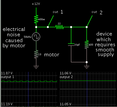
There's a chance a resistor is all you need to provide some degree of isolation. Add a smoothing capacitor.

This simulation portrays the concept.

1854167600_1412386417.png


An inductor will help, of course. If you use one, then you can reduce the smoothing capacitor.
 

There's a chance a resistor is all you need to provide some degree of isolation. Add a smoothing capacitor.

This simulation portrays the concept.

1854167600_1412386417.png


An inductor will help, of course. If you use one, then you can reduce the smoothing capacitor.

Thanks for your example.
Two questions:

1- Which program have you used to simulate that ?
2- Depending of the current, the resistor will dissipate too much heat. For better performance I can replace it by an inductor. How can I calculate the inductor's value ?
 

The motor will tend to introduce ground noise which can't be readily filtered by a single inductor in the power line. You may have to also use a common-mode choke connected in series with both the power and ground connections to the sensor to help filter out the noise.
 

Thanks for your example.
Two questions:

1- Which program have you used to simulate that ?

This is Falstad's interactive animated simulator. Free to download and use at:

www.falstad.com/circuit

2- Depending of the current, the resistor will dissipate too much heat. For better performance I can replace it by an inductor. How can I calculate the inductor's value ?

Your figure of 470 uH is similar to my result, via the formula:
XL = 2 Pi f L
or,
L = 600 / (2 * Pi * 200k)

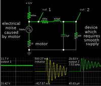
Adding an inductor will only help if you also add a filter capacitor. However when we do that, my simulation reveals wide oscillations at startup. It is theoretical, of course, since it depends on characteristics in the inductor such as saturation, etc.

Your sensor circuitry may or may not endure the raised volt levels.


If you'd like to see the same circuit in action...

Falstad's can export a link containing an entire schematic. Click this link to:

(1) open the falstad.com website,
(2) load my schematic (above), and
(3) run it on your computer. (Click allow to install the Java applet.)

https://tinyurl.com/od57stg

You can change values by right-clicking a component, and select Edit.

You can add and delete components, etc.
 

Status
Not open for further replies.

Similar threads

Part and Inventory Search

Welcome to EDABoard.com

Sponsor

Back
Top