Continue to Site

Extended range for TL431 voltage reference

riscv

Newbie level 6
Joined
Mar 24, 2025
Messages
12
Helped
0
Reputation
0
Reaction score
0
Trophy points
1
Activity points
80
Hi,

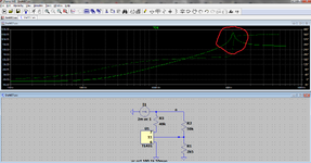
I designed a circuit to extend the range of the TL431 programmable voltage reference IC.

tl431.gif


The IC is rated at 36V (cathode to anode maximum voltage) and its reference voltage is 2.5V.

Do you see any flaws in the circuit above?
 
Hi,

you gave no working conditions and no specifications.

I guess you want it to output 52.5V at the collector of the BJT ... but to what? What is the load and what is it´s operating range?

In case it draws more than 1mA .. the voltage will break down.
In case it draws 0.75mA .. the voltage at the TL431 cathode is expected to be more than 42V .. which already violates the specifiation!

Klaus
 
Wow, thank you very much for your insights! (and @danadakk for the simulation).

The final circuit is a battery (64V) voltage measurement:

ref_volt_v2.gif


The components values are not accurate though, it's just a proof of concept.

I actually need a reference voltage of about 40V and I could set up a current source value of 5 mA or smth.

I just wanted to get a broader range for the battery voltage output signal (toward the uC ADC).

PS: Sorry for the delay, my postings are moderated.
 
Last edited:
Hi,

I still can´t see what your circuit is supposed to do.
Especially the new circuit and the text about "Battery voltage measurement", "broader range for the battery voltage output", "I actually need a reference voltage of about 40V"... and so on makes no sense to me.

Instead of a lot of confusing text, I expect clear numbers, formulas ...

Klaus
 
Presuming post #7 circuit is the final application, I'm rather sure there's a better way to achieve what it does (implement a certain input to vbat voltage transfer function). But instead of guessing about intended function, I prefer to hear a specification first.

Implicite post #1 question seems to be: Is TL431 safe?
My answer, only conditionally, I'd never trust that all conditions are met. Better design an intrinsically safe circuit. Returns to above point, what's the purpose, how can it be achieved in a straight way?
 
I want to measure the voltage of a lead-acid battery bank (48V nominal, 42-64V operational range).

In order to get more accurate readings, I want to substract a reference voltage (40V) and then convert the remaining 2-24V range into 0-3.3V range (ADC).

I guess this could be achieved with the circuit above. Do you have any other suggestions?


LE: Here's the original schematic (post #1) with the actual component values. @FvM, could you elaborate on untrusting operating conditions of TL431? R1 current will always be around 1 mA and the R4 (and TL431 K-A) current will be 4 mA, hence the voltage drop across R4 will be 30V.

tl431v1.gif
 
Last edited:
Hi,

so you want:

V_ADC = (V_Bat - 40V) / 7.273

A lot of effort, ... just to gain a bit more than 1 LSB .. in ideal case.

The 40V is how accurate? The resistors have what tolerance?

Please do an error calculation.
I bet you gain almost nothing .. if not getting worse results.
In my eyes it´s not worth the effort.

***

And then you talk about an 3.3V ADC input range.
This let´s me guess that you use VCC (3.3V) as the reference for the ADC. If so ... this reference may cause a more than 10 times bigger error than anything else.

VCC of 3.3V isn´t 3.3000 Volts. It has initial inaccuracy and drifts with time, with temperature, with load current. .. and usually contains a lot of noise.

***
Again: please do an error analys of the whole system .. including VRef and even GND bounce.
This analysis shows where the biggest errors are. And you should start your (hardware) optimization at the biggest error sources.

Klaus
 
I could supply a stable voltage reference to the ADC. Anyway, those details (max ADC voltage input and so on) are not related to the circuit above.

And why do you think I will only get an extra LSB of accuracy? Instead of converting a subset (42-64) of a 0-64V range into a subset of a 0-3V one, this circuit converts a 2-24 range into an almost full 0-3V range. Am I missing something on increased accuracy?

LE: I could replace R4 with a 30V zener diode (for extra safety).
 
Last edited:
I want to measure the voltage of a lead-acid battery bank (48V nominal, 42-64V operational range).

In order to get more accurate readings, I want to substract a reference voltage (40V) and then convert the remaining 2-24V range into 0-3.3V range (ADC).
A single OP in difference amplifier configuration (Uout = A*U1 - B*U2) plus a stable reference source can do the same.
 

    riscv

    Points: 2
    Helpful Answer Positive Rating
And why do you think I will only get an extra LSB of accuracy?
You have to compare "ranges".
the absolute battery voltage range is 0..64V
your measurable battery voltage now is 24V

64V/24V = 2.666 which equals to 1.4 bits

I can only repeat: do an error calculation.

Klaus
 
A single OP in difference amplifier configuration (Uout = A*U1 - B*U2) plus a stable reference source can do the same.
I guess you're right, I was just trying to keep it simple and reliable (by avoiding any unnecessary ICs, though TL431 itself it's such a "vulnerability").

I'll try an alternate design using an instrumentation opamp, thank you once again for your advice.

But as a proof of concept, the presented circuit could actually work without flaws, right?
 
I can see the intent of the circuit, but also would guess doing the subtraction after attenuating the battery voltage would be the better approach.

It comes down to comparing different sources of error. Would need to do a fairly sophisticated analysis with realistic component models to really compare.
 

    riscv

    Points: 2
    Helpful Answer Positive Rating


Write your reply...

LaTeX Commands Quick-Menu:

Similar threads

Part and Inventory Search

Welcome to EDABoard.com

Sponsor

Back
Top