Welcome to our site! EDAboard.com is an international Electronics Discussion Forum focused on EDA software, circuits, schematics, books, theory, papers, asic, pld, 8051, DSP, Network, RF, Analog Design, PCB, Service Manuals... and a whole lot more! To participate you need to register. Registration is free. Click here to register now.
Hi everyone.
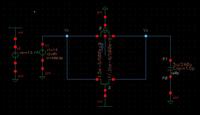
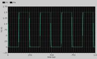
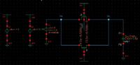
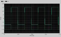
The transmission gate(fig1) is powered from 0-1.5V, the simulation results (fig2) are good. But, when I powered it between ± 1.5V (fig3), the low level is poorly transmit(Fig4). I ask if someone can explain these results.
The NMOS transmits the '0' and the back-gate (body/substrate) is at 0V and thus won't pass -1.5V very well. There will also be parasitic diodes set up by these voltage levels. In general the substrate really should be tied to the lowest voltage supplied to the chip.
Hi Old Nick,
you want to say that there are other models of NMOS with a variable Substrate but in our thecno there doesn't exist.
Realy, this transmission gate(TG) is used in a switched capacity(SC) integrator which is powered betwen +-1.5V, do you think that this problem (of Substrate) can affects the functioning of the integrator?
"I will try it now"
I'm surprised that there isn't a model of NMOS with a body connection, try searching through a few different libraries.
If your substrate is tied to 0V and you're trying to pass 0V then it will be a problem. There may be way's round this in the sim.
When you layout NMOS devices you have the choice of connecting the source and body together or source to some-other voltage and the body to GND (this gives rise to the body effect).
Added after 4 minutes:
I've just realised I've been talking rubbish.
It's your PMOS that is passing the 0!
I'll have a bit of a think and get back to you.
Added after 5 minutes:
Looking at you're graph again, it does look like it is about a threshold voltage out. I'll just try and sim it myself and see if I can fathom what is going on.
Added after 21 minutes:
Here's the sim and the circuit I used, and it works.[/img]
I'm sure that the problem comes from the NMOS and you are right: it comes from the substrate effects.
Because, when i simulate only the NMOS as a switch, I have the same problem
i think so. I've never fed a -ve voltage to a chip before, and I'm not sure how the models will treat parasitic diodes etc.. But the PMOS should passing the 0 (-1.5V), an NMOS won't pass a zero at all (it wil get to within a threshold of it (which is what you're seeing).
It may be that your PMOS is not turning on, I'm not sure why though, the substrate is connected to +1.5 and the gate is connected to -1.5V so it should be OK? try removing the NMOS and just passing -1.5 with the PMOS.
Just realised i wasn't talking rubbish the first time, I'm talking rubbish now, the NMOS transmits the 0.
I need a lie down, I was up too early this morning and to bed to late. My word!!!
I iunderstood that the solution is to connect the substrat of the NMOS to the VSS (-1.5V) but our techno not able to be powered between ±1.5. So, I will work with 0-3V
This site uses cookies to help personalise content, tailor your experience and to keep you logged in if you register.
By continuing to use this site, you are consenting to our use of cookies.