Continue to Site

Welcome to EDAboard.com

Welcome to our site! EDAboard.com is an international Electronics Discussion Forum focused on EDA software, circuits, schematics, books, theory, papers, asic, pld, 8051, DSP, Network, RF, Analog Design, PCB, Service Manuals... and a whole lot more! To participate you need to register. Registration is free. Click here to register now.

esp 01 support needed

johnny78

Full Member level 5
Full Member level 5
Joined
Jun 28, 2017
Messages
256
Helped
1
Reputation
2
Reaction score
4
Trophy points
1,298
Activity points
3,337
hi Guys
i've bought esp 01 long time ago but i couldnt test it & now im looking for some informations about it
some sites say it must work on 3.3v other tutorials says it works on arduino uno 5v signal level
im confused even my FTDI converter has switch to convert between 3.3 or 5v but when im testing with DVM its always 5.7v

this is the FTDI i have
https://www.okuelectronics.com/store/programmers/ft232rl-ftdi-usb-to-ttl-serial-module/

any good guide to start will be great

thanks
Johnny
--- Updated ---

hi Guys
i've bought esp 01 long time ago but i couldnt test it & now im looking for some informations about it
some sites say it must work on 3.3v other tutorials says it works on arduino uno 5v signal level
im confused even my FTDI converter has switch to convert between 3.3 or 5v but when im testing with DVM its always 5.7v

this is the FTDI i have
https://www.okuelectronics.com/store/programmers/ft232rl-ftdi-usb-to-ttl-serial-module/

any good guide to start will be great

thanks
Johnny
i ws checking the FTDI site & i see this info

FTDI FT232RL USB to TTL Serial Adapter Module 3.3V/5V Switch Selectable Logic Levels

so do you thinks i must power it from 3.3v & use just the signal of the FTDI?
--- Updated ---

hi Guys
i've bought esp 01 long time ago but i couldnt test it & now im looking for some informations about it
some sites say it must work on 3.3v other tutorials says it works on arduino uno 5v signal level
im confused even my FTDI converter has switch to convert between 3.3 or 5v but when im testing with DVM its always 5.7v

this is the FTDI i have
https://www.okuelectronics.com/store/programmers/ft232rl-ftdi-usb-to-ttl-serial-module/

any good guide to start will be great

thanks
Johnny
--- Updated ---


i ws checking the FTDI site & i see this info

FTDI FT232RL USB to TTL Serial Adapter Module 3.3V/5V Switch Selectable Logic Levels

so do you thinks i must power it from 3.3v & use just the signal of the FTDI?
the datasheet of the esp01 mentioned that it needs 80ma current which arduino uno 3.3v cant supply this current
https://www.alldatasheet.com/datasheet-pdf/pdf/1179098/ETC2/ESP-01.html

im more confused now
--- Updated ---

ةخقث ؤخىبع
hi Guys
i've bought esp 01 long time ago but i couldnt test it & now im looking for some informations about it
some sites say it must work on 3.3v other tutorials says it works on arduino uno 5v signal level
im confused even my FTDI converter has switch to convert between 3.3 or 5v but when im testing with DVM its always 5.7v

this is the FTDI i have
https://www.okuelectronics.com/store/programmers/ft232rl-ftdi-usb-to-ttl-serial-module/

any good guide to start will be great

thanks
Johnny
--- Updated ---


i ws checking the FTDI site & i see this info

FTDI FT232RL USB to TTL Serial Adapter Module 3.3V/5V Switch Selectable Logic Levels

so do you thinks i must power it from 3.3v & use just the signal of the FTDI?
--- Updated ---


the datasheet of the esp01 mentioned that it needs 80ma current which arduino uno 3.3v cant supply this current
https://www.alldatasheet.com/datasheet-pdf/pdf/1179098/ETC2/ESP-01.html

im more confused now
more confusing articles

https://forum.arduino.cc/t/connection-uno-with-esp01/1198688/11
 
Last edited:
Writing posts seem to be really difficult ...

Arduino UNO has nothing to do with it ..... unless you connected it somehow.

I did not read through the datasheets ... but supply voltage is the most important specification ... thus I expect it to be specified clearly.

Klaus
 
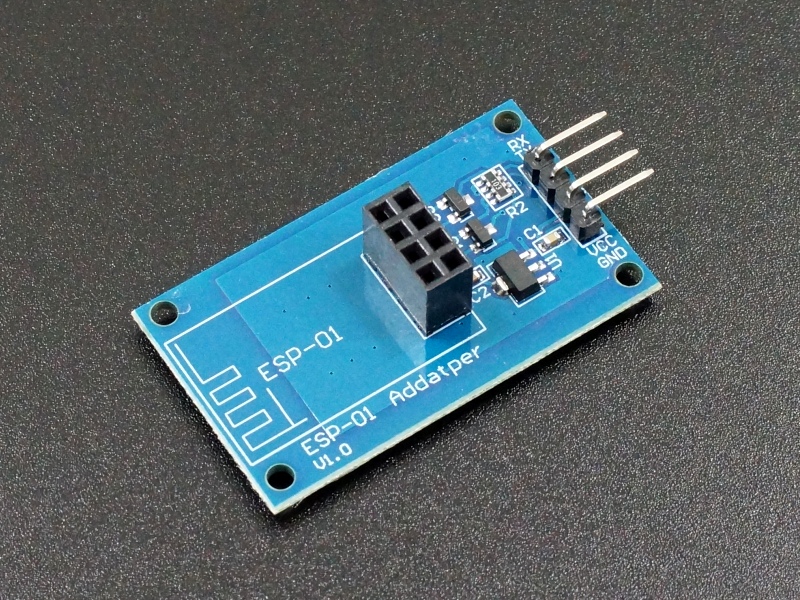
ESP01 is 3.3v...
except if you use some adapter like this one

ESP8266-ESP-01-Adapter-Module-2.jpg
 
Confirmed - if you power it with more than about 3.6V you get smoke! Many of the development boards have regulators on them that drop 5V from a USB socket to the 3.3V needed by the ESP8266 MCU.

The ESP01 is a tiny board without a regulator so you must feed it 3.3V from outside.

Excellent devices but with only three I/O pins on the ESP01 it it very limited if you want to interface to other things. I use lots of ESP8266 but the bare IC on my own PCBs.

Brian.
 
ESP01 is 3.3v...
except if you use some adapter like this one

ESP8266-ESP-01-Adapter-Module-2.jpg
hi Sir
yes i read about this adapter
can i build it? because i cant get it here
can i use 3.3v regulator & & a voltage devider for Tx & Rx line ?

thanks
--- Updated ---

--- Updated ---

Confirmed - if you power it with more than about 3.6V you get smoke! Many of the development boards have regulators on them that drop 5V from a USB socket to the 3.3V needed by the ESP8266 MCU.

The ESP01 is a tiny board without a regulator so you must feed it 3.3V from outside.

Excellent devices but with only three I/O pins on the ESP01 it it very limited if you want to interface to other things. I use lots of ESP8266 but the bare IC on my own PCBs.

Brian.
i dont like smoke

i will build this adapter
https://protosupplies.com/wp-content/uploads/2018/06/ESP8266-ESP-01-Adapter-Schematic.jpg
can i use any N channel Mosfet ?
 
Last edited:
That adapter should be fine, it is basically the same regulator all the development boards use and the same circuit the 'level converter' boards use. You can simplify it a little because the 5V signal going to the ESP01 RX pin can be dropped using just two resistors, for example 1K in series with the signal and 1.5K on the RX pin side to ground. You still need the MOSFET or similar circuit to step the 3.3V TX signal up to 5V.

In theory, a 3.3V high level will suffice to be seen as a logic high by a 5V device but there will be impaired noise immunity, it is better to use a level shifter. As the TX signal is output only, you can use a bipolar NPN transistor instead. Connect its emitter to the ESP01 TX pin, connect the base to 3.3V through a resistor (suggest 2K2) and the collector to 5V through say 2K2. Take the output from the collector. The idea is that if TX is high there will be no (or very little) voltage between base and emitter so the transistor does not conduct and the collector is pulled high to 5V. When TX is low, the transistor is forced into conduction because there is now bias current so the collector voltage drops close to that of the TX pin. In real life the TX pin will never reach exactly zero and there will be some voltage drop across the transistor so the output level will still be some small voltage but it will be well below 5V logic threshold.

The BSS138 is chosen because its gate threshold voltage is guaranteed to be lower than 1.5V so it will always interface to 3.3V circuits, that's why they call it a "logic level MOSFET". Some MOSFETs have much higher Vgs threshold and may not turn on with only 3.3V.

Brian.
hi Brian

i've got this today & i will test tomorrow morning

https://www.tinytronics.nl/en/commu...ial/usb/esp-link-esp8266-esp-01(s)-programmer
 
That looks perfect. I have a similar one here but mine has a manual switch so it can be used as a programmer or a UART interface, the one you have has the programming selector on-board but can't be used as a UART.

I would suggest you make an adapter if you plan on using ESP8266 (or ESP32) devices in the future. If you construct a plug or socket to fit the one on your programmer with flying wires, you can use it to program other ESP device while they are in-circuit on other boards.

Brian.
 
The ESP8266 must be run from 3.3V as 5V will destroy it, further the IO voltage must be 3.3V or you will damage the ESP8266. The FTDI converter has selectable logic levels, but I advise you to check the voltage levels before connecting to the ESP8266. If the IO levels are 5V it is easy to change this to 3.3V by using a voltage divider of a 1K dropper resistor followed by a 1K2 resistor to ground. note you cannot use higher values as shown in some sites and books as the firmware enables pull up resistors on the inputs. Note the 3.3V from the FTDI converter cannot supply enough current to the ESP8266 as it can only supply 50mA where as the ESP8266 requires around 160mA when transmiting.
 
Last edited:
l
That looks perfect. I have a similar one here but mine has a manual switch so it can be used as a programmer or a UART interface, the one you have has the programming selector on-board but can't be used as a UART.

I would suggest you make an adapter if you plan on using ESP8266 (or ESP32) devices in the future. If you construct a plug or socket to fit the one on your programmer with flying wires, you can use it to program other ESP device while they are in-circuit on other boards.

Brian.
hi Brian

lets say im happy i could upload blink sketch & its working
& my adapter has a manual push button on the side which i didnt know yet what the purpoe of it
when i understand full functionality about it i will make an adapter for everything needed later

do you suggest good informations source to start use the wifi module
i figured that i have an Node MCU V3 board also & i've tested on it before testing the esp01 so is it the same code if i want to use anyone of them?
except the GPIO of course

thanks
Johnny
--- Updated ---

The ESP8266 must be run from 3.3V as 5V will destroy it, further the IO voltage must be 3.3V or you will damage the ESP8266. The FTDI converter has selectable logic levels, but I advise you to check the voltage levels before connecting to the ESP8266. If the IO levels are 5V it is easy to change this to 3.3V by using a voltage divider of a 1K dropper resistor followed by a 1K2 resistor to ground. note you cannot use higher values as shown in some sites and books as the firmware enables pull up resistors on the inputs.
thanks for information im happy i didnt test it before get the right adapter
i will need this information when connecting to other microcontroller as WiFi module using Rx & Tx pins
 
i figured that i have an Node MCU V3 board also & i've tested on it before testing the esp01 so is it the same code if i want to use anyone of them?

Being the code made in Arduino, you don't care about that, it's the purpose of the platform to be compatible with the same familly board. Note however that some of these modules have one or other additional I/O;, you need to check by yourself.
 

LaTeX Commands Quick-Menu:

Similar threads

Part and Inventory Search

Welcome to EDABoard.com

Sponsor

Back
Top