Continue to Site

Welcome to EDAboard.com

Welcome to our site! EDAboard.com is an international Electronics Discussion Forum focused on EDA software, circuits, schematics, books, theory, papers, asic, pld, 8051, DSP, Network, RF, Analog Design, PCB, Service Manuals... and a whole lot more! To participate you need to register. Registration is free. Click here to register now.

error message in CST while simulation.

Status
Not open for further replies.

vishal_sonam

Full Member level 3
Full Member level 3
Joined
Jan 19, 2012
Messages
187
Helped
14
Reputation
28
Reaction score
14
Trophy points
1,298
Visit site
Activity points
2,457
Hello, I am new to CST.
I am simulating my antenna for the frequency 1-40GHz.
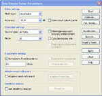
But when I am simulating my antenna I am getting this message. "Some higher propogating modes at port 1 are not considering in time domain calculation. This possibly leads to an inaccurate energy balance. Consider to increase the number of modes or decrease the upper frequency limit"
After this I increase the number of modes and calculated only modes but now I Don't know where to see the result of calculated modes.
Please somebody help me about this.
Thanks.
 

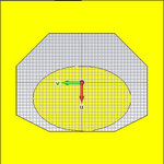
Post a pic of your simulation setup. Maybe your waveguide port, if you use some, has not the right dimension.
 

I have attached the images.
The width of feed line is 3mm and the substrate size is 1.6mm
Thanks
 

Attachments

  • waveguide port_setup.jpg
    waveguide port_setup.jpg
    44.7 KB · Views: 178
  • Time Domain Solver.jpg
    Time Domain Solver.jpg
    52.8 KB · Views: 128

It's not a problem, but let's continue in this forum, maybe other users have a similar problem.
 
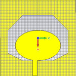
I have attached the images and I have attached the comparison of measured and simulated results of an antenna on which I am working. The simulated S11 parameter is from CST. The measured and simulated results are matching upto 22Ghz but after that from 22- 34 Ghz the results are not mtaching.Is this any CST problem? or setting I have to change for higher frequencies.? Is this the problem of no of modes in CST?
 

Attachments

  • ground plane.jpg
    ground plane.jpg
    36.1 KB · Views: 114
  • front.jpg
    front.jpg
    69.4 KB · Views: 110
  • S-Parameters_04 June.pdf
    24.5 KB · Views: 180

There are a couple of reasons: First, how do you connected your antenna to your measurement device? Some connector? The influence of the connector is not taken into account in your simulation if you used only a waveguide. Second, reduce the lateral extension of your waveguide, try -6..6. What are your boundary settings? Did you used adaptive meshing? Is it a pcb antenna? What substrate you used. What is the material of metallization in your simulation? You see, a lot of questions :).
 

I connected my antenna to the measurement device by the connector. The substrate used for antenna is FR4 and as I am very new to the CST so I did not know about the adaptive meshing and all.
that is why I was asking your email address.
can I still have your email address so that you can check my design and tell me the necessary changes. and then i will simulate it myself.
Please do this for me I really need.
Thanks
 

You really took FR4 for 40 GHz? The problem of FR4 is its anisotropic permittivity. As rule of thumb, take FR4 up to 1-2GHz. So in this case, maybe your measurement is wrong. The "bad" behavior of FR4 is not included in CST. And about adaptive meshing and so on, everything is explained in the manual. Please don't misunderstand but at the moment I think we should continue in the forum.
 

well, if you see the measured results so yes I am getting UWB between 1-34GHz and upto 32 GHz there is satisfactory match between simulated and measured results but after 32 GHz, the simulated results going more downward and not meeting at -10dB and the measured results meeting -10dB at 32 GHz so I was wondering that why simulated results not meating -10db anywhere like measured results.
Thanks anyways:)
 

Because your simulation predicts a better performance because it does not take real-world behavior (FR4, connector, etc.) into account. And if you have really good match between sim. and meas. is questionably. Because you just consider the absolute value of s11. And -10 dB just means you have a VSWR of around 2:1.

Read in the manual how to simulate (adaptive meshing), prove the results of your measurements (maybe a second measurement with another antenna). Because I think it's not only your simulation.

One hint: Reduce the accuracy in your simulation setup to -40db and just activate the adaptive meshing with default values and than you can compare both simulation results.
 

You really took FR4 for 40 GHz? The problem of FR4 is its anisotropic permittivity.

... and in general, large tolerances on permittivity and other material properties.

And another problem is high dieelectric loss. Not sure if this antenna is actually radiating much, or is just a lossy resonator. It will be interesting to see the radiation efficiency.
 

I will put the image of radiation efficiency here once I learn how to plot the graph of radiation in CST. I am new to CST so just learning these days.
 

Status
Not open for further replies.

Similar threads

Part and Inventory Search

Welcome to EDABoard.com

Sponsor

Back
Top