Continue to Site

Welcome to EDAboard.com

Welcome to our site! EDAboard.com is an international Electronics Discussion Forum focused on EDA software, circuits, schematics, books, theory, papers, asic, pld, 8051, DSP, Network, RF, Analog Design, PCB, Service Manuals... and a whole lot more! To participate you need to register. Registration is free. Click here to register now.

ENOB and SNDR of the R-2R DAC versus the input frequency

Status
Not open for further replies.

r.mirtaji

Junior Member level 3
Joined
Feb 9, 2020
Messages
27
Helped
0
Reputation
0
Reaction score
0
Trophy points
1
Activity points
403
i designed an Eight-bit digital-to-analog converter based on MOSFET
In order to check the dynamic performance of the converter, I have used the following circuit
The characteristics of the converter are as follows:
Fin=2.451171875000000e+06 (input frequency)
Fs=10M (sample frequency)
N=1024; (Number of sample)

1671296990900.png

The dynamic characteristic is obtained as follows
Fin=2.5M ====><<ENOB=7.9859418 , SINAD=49.83831 , SFDR=66.166519>>
1671298628078.png

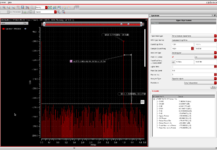
When I change the input frequency, the dynamic characteristic does not change and is almost constant!
Fin=4M ====><<ENOB=7.9859418 , SINAD=49.83831 , SFDR=66.166519>>
1671351375785.png
1-Shouldn't the ENOB and SFDR decrease by increasing the input frequency?
2-To express the performance of the converter, do we draw the graph of
the ENOB according to the frequency or the ENOB according to the sampling frequency
1671352465946.png

1671352567269.png

Why doeas the ENOB and SFDR not decreased with increasing frequency?

1671352818718.png

The converter circuit is as follows
 

You have grounded output and measure current to ground. It is rather unusual configuration. So, you are limited by ft of transistors which may be in tens of GHz range.
Add a proper load to the output. In your case it might be needed to use opamp as this kind of DAC requires equal voltage at the outputs.
The simplest way is to use svcvs source (voltage controlled voltage source with Laplace transfer function), define single pole response with reasonable bandwidth, resistor in feedback and capacitive load at the output. You may also want to add expected capacitance to input of opamp model.
Shouldn't increasing the input frequency decrease sinad and thus enob?
according to the relationship:
ENOB = (SINAD - 1.763)/6.02
SINAD is the ratio of total signal power to the noise-plus-distortion power. It is calculated using the following
algorithm:
SINAD=10 log (S/N+D)
Does the denominator of the sinad fraction, which is the sum of noise and distortion, not change?
Does the denominator of the sinad fraction, which is the sum of noise and distortion, not change when the input frequency changes?
according to you Only the ft of the converter ladder transistors causes a limitation in sinad and enob of the converter.
--- Updated A moment ago ---

When the input frequency changes, the resulting harmonics are also shifted, and with the increase in frequency, some harmonics may be moved out of the Nyquist band.
I changed the input frequency from 1Mhz to 5Mhz, but the snr and sinad did not change, the sampling frequency is also 10Mhz
Should I change the input frequency or the sampling frequency for this analysis?
 
Last edited:

Hi,

algorithm:
SINAD=10 log (S/N+D)
This is correct.
Now you change the frequency ... but there is no frequency in the formula. Means the result is independent of frequency.
What do you expect?

S = signal amplitude
N = noise amplitude
D = Distortion. Did you "simulate" frequency dependent distortion?

Klaus
 

Since the harmonic is always a multiple of the fundamental frequency
When we increase the input frequency The harmonic exceeds the Nyquist frequency (FS/2) and thus cause a reduction of power distortion
And as a result, it reduces sinad and ENOB
In most PAPER, the ENOB diagram is drawn in terms of the input frequency, which decreases the ENOB as the input frequency increases
AND ALSO
the SFDR diagram is drawn in terms of the input frequency, which decreases the SFDR as the input frequency increases
But here both SFDR and ENOB characteristics are constant with increasing frequency

Hi,


This is correct.
Now you change the frequency ... but there is no frequency in the formula. Means the result is independent of frequency.
What do you expect?

S = signal amplitude
N = noise amplitude
D = Distortion. Did you "simulate" frequency dependent distortion?

Klaus
--- Updated ---

1671365102880.png

Amplitude refers to the voltage or current level of signals at a given frequency:
in this analysis
Amplitude of fundamental
-100dB=20Log(Im)===>Im=10uA
frequency of fundamental
F_Iout=2.4512Mhz
------------------------------------------
Spurs—Spurs, also known as device spurs, are frequency components that appear in
signals because of the electrical components of the instrument. Some examples ,
leakage of oscillator clock signals, Clock feedthrough
1671366171142.png

Harmonics, or harmonic frequencies, are frequencies that are integer multiples of the fundamental frequency. Harmonics are often not part of the actual signal, but appear due to Nyquist sampling theory and transmission line reflection
Hn=n*F(fundamental )=>2*4512Mhz=4.9024Mhz
------------------------------------------------------------------------
SFDR is the usable dynamic range before spurious noise interferes with or distorts the fundamental signal. The equation used to calculate SFDR is the measure of the ratio in amplitude between the fundamental signal and the largest related spur from DC to the full Nyquist bandwidth.
SFDR=66.165
 
Last edited:

Since the harmonic is always a multiple of the fundamental frequency
I guess you used ideal digital values, thus there is no "distortion" in the digital value. No overtones.
Does your switching DAC include some "nonlinearities" that cause overtones?
I asked before "do you simulate frequency dependent distortion"?
I mean: A simulation does only simulate what you tell it to do.

With AD converters every frequency above nyquist becomes an alias frequency, but the amplitude does not get reduced.Nor does the combined RMS change.

With a "switched" DAConverter... (without an analog post filter) it is similar. It surely causes sone "switching noise". But as long as you don't use an analog post filter - you just shift the frequencies but not amplitueds and nor the RMS.

*******
Example:
Let's assume you don't use ideal sine values, but square wave instead. (I know this is not what you want to do)
Sample rate always is 10MSPS.
Now let's say you use a 1kHz square wave. So 1kHz fundamental, + overtones: 3 kHz, 5kHz, 7kHz...
Nothing is to suppress the overtones, so you get a defined signal_to_overtones ratio.(if I'm not mistaken 100% fundamental + 44% overtones)
No change from 1kHz to 1MHz. So 1MHz fundamental, + overtones: 3 MHz, 5MHz, 7MHz...
--> you get the same signal_to_overtones ratio as with 1kHz

But as soon as you use an analog post filter everything changes:
Let's say you use a 5MHz post filter.
With a 1kHz signal you get the fundamental and all overtones up to the 500th about not suppressed.
The signal_to_overtone ratio does nit change much with respect to the non filtered signal
But using a 1MHz signal, now you get the 3rd overtone about not suppressed, the 5th is suppressed to 70% and every higher overtone is even more suppressed.
Now the signal_to_overtone changes a lot with respect to the unfiltered value. And with respect to the 1kHz signal.
The S/N R now is frequency dependent ... because you use an analog post filter.

The question is "what" exactly do you simulate?

Klaus
 

1671366975194.png

Is it necessary to activate the TRANSIENT NOISE option for TRANSIENT ANALYSIS and then running SPECTRUM?
I guess you used ideal digital values, thus there is no "distortion" in the digital value. No overtones.
Does your switching DAC include some "nonlinearities" that cause overtones?
I asked before "do you simulate frequency dependent distortion"?
I mean: A simulation does only simulate what you tell it to do.

With AD converters every frequency above nyquist becomes an alias frequency, but the amplitude does not get reduced.Nor does the combined RMS change.

With a "switched" DAConverter... (without an analog post filter) it is similar. It surely causes sone "switching noise". But as long as you don't use an analog post filter - you just shift the frequencies but not amplitueds and nor the RMS.

*******
Example:
Let's assume you don't use ideal sine values, but square wave instead. (I know this is not what you want to do)
Sample rate always is 10MSPS.
Now let's say you use a 1kHz square wave. So 1kHz fundamental, + overtones: 3 kHz, 5kHz, 7kHz...
Nothing is to suppress the overtones, so you get a defined signal_to_overtones ratio.(if I'm not mistaken 100% fundamental + 44% overtones)
No change from 1kHz to 1MHz. So 1MHz fundamental, + overtones: 3 MHz, 5MHz, 7MHz...
--> you get the same signal_to_overtones ratio as with 1kHz

But as soon as you use an analog post filter everything changes:
Let's say you use a 5MHz post filter.
With a 1kHz signal you get the fundamental and all overtones up to the 500th about not suppressed.
The signal_to_overtone ratio does nit change much with respect to the non filtered signal
But using a 1MHz signal, now you get the 3rd overtone about not suppressed, the 5th is suppressed to 70% and every higher overtone is even more suppressed.
Now the signal_to_overtone changes a lot with respect to the unfiltered value. And with respect to the 1kHz signal.
The S/N R now is frequency dependent ... because you use an analog post filter.

The question is "what" exactly do you simulate?

Klaus
The digital-to-analog converter circuit is of r-2r current based on MOSFET transistor.
1671372117586.png

Transistors m2 and m3 act as switches that transfer the current according to the input digital code to the output terminals.
The gate voltage of m2 and m3 transistors is supplied from the ideal digital to analog converter output
(Transistors m2 and m3 don't create non-linearity when they switch)
There is no S0,S1,Sn key THE gate of m2 and m3 transistors connect directly to output pin of ideal ADC
1671372769850.png


1671373002837.png

1671373208267.png


Do you mean that instead of connecting the DAC input directly to the ADC output, I should use a transistor as a switch or use an inverter circuit between the gates of the transistors t3 and t4 as shown below? And in this case, the harmonics of The input sinusoidal signal appears at the output.?
that is harmonics have not appeared in the output yet, should the harmonic amplitude always be greater than spure and noise
-------------------------------------------------
From the example you gave, I realized that the low-pass that is placed in the output of the DAC
reduces SFDR and SINAD, and the reason is the attenuation of the range of harmonics.
Why are the input frequency sfdr ratio curve or the input frequency enob ratio curve used to measure dac performance in the articles?
In this way, this is directly related to the order of the filter, with which coefficient to perform the attenuation.
 
Last edited:

Status
Not open for further replies.

Part and Inventory Search

Welcome to EDABoard.com

Sponsor

Back
Top