Continue to Site

Welcome to EDAboard.com

Welcome to our site! EDAboard.com is an international Electronics Discussion Forum focused on EDA software, circuits, schematics, books, theory, papers, asic, pld, 8051, DSP, Network, RF, Analog Design, PCB, Service Manuals... and a whole lot more! To participate you need to register. Registration is free. Click here to register now.

ENERGY MEASURE WITH AN OSILOSCOPE

Turgay Abay

Newbie level 4
Joined
Oct 25, 2023
Messages
6
Helped
0
Reputation
0
Reaction score
0
Trophy points
1
Activity points
44
Hello friends.

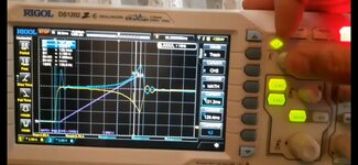
I almost became sure that we can measure of a Electrical wawe pulse''s spent energy with multiply Voltage and Current and take the result's integral with Osiloscope MATH function . I am working for a special experiment shown at picture ( Not translated to English yet and red text is enough for questions ).In the experiment we are giving DC current for a very short time (about 100-200 ms) and measuring

1- How much energy TOTAL spent ?
2-How much energy spent for COIL HEAT LOSSES? ( COIL'S resistance is 1 ohm ) For second question i multiplied current x current and i accepted the result wawe as a power wave again like first question's answer (because R=1 ohm and I x I = I x I x 1(R) = I.V) then i took the integral with scope again for energy measuring

1-..DO YOU SEE ANY MISTAKE about circuit or measuring way ?
2- Have you got easier way to measure these?

1697832849611_bjboxm_2_0.jpg
 
Hi,

some considerations.

You said "I".
* it needs to be I(t). The momentary I.
* you can´t use I(avg)

You said "R = 1 Ohms".
* be sure the shunt is resistive in the rage of frequency you expect.
* better avoid wire wound resistors (they have high series inductance)

You said "DC current for a very short time"
* this contradicts itself.
* if it is DC then it needs to be continous. No ON and no OFF
* if it is "for a short time", then it includes a lot of frequencies (somehow the opposite fo DC)

You said: "2-How much energy spent for COIL HEAT LOSSES?"
* this only works for true DC (see above)
* but as soon as you work with pulses the current is also used to increase/decrease the magnetic field, which also is energy. 0.5 x L x I x I is stored as magnetic energy.

Klaus
* Hi .Thanks for detailed returning. Yes , right .We already use momentary I and V I(t), V(t) , not avg or RMS
*Total time is about 140 ms so Resistance is in the range of frequency
*Yes it is bot constant true DC but the direction of current is not changing here.So we can accept the circuit and current like " RL Circuit with DC "
*I thought it like this because it is just like a short time in a DC Electrical Motor with Permanent Magnet. This pulse wave is similar with a part of period of this motor.Here for motor the waves and current are not true DC but we still use I²x Rx t for measure heat losses energy
*We already measure all the energy types as TOTAL for COIL . FOR HEAT LOSSES ; Wound resistsor's inductance is about 2 microH and it stores less than 0.001 joule( f= 7 Hz , I=6 A ) so it wont change any result for me when i compare it with total energy (I found it as about 4 joule for total )or heat losses (About 3.5 joule ).This also wont make an important change for the total resistance of shunt resistor because inductive resistance is nearly zero( less than 0,001 ohm ) when we compare it 1 ohm
 
This waves are from one the measurement Yellow is for current ,Blue ia for voltage
 

Attachments

  • Screenshot_20231020-121819_Video Player.jpg
    Screenshot_20231020-121819_Video Player.jpg
    890.2 KB · Views: 33
Hi,

yellow is current: Then the scope picture makes no sese to me.

I don´t see why the current goes up 3 divisons within a couple of milliseconds.
I don´t see why the current should drop after some tens of milliseconds.

I expect the current to startt at zero and then start to rise. The starting rise rate should be about V/L.
I expect the current to rise ... then approximate a horizontal line, never drop. (as long as the switch is closed)

Klaus
 
What did you measure for L.main and L.mini and DCR?

I expect dI/dt=L/R R=DCR+1ohm (sense)

There is also kinetic energy being measured expect some back EMF rising at the end to reduce current.
 
Hi,

yellow is current: Then the scope picture makes no sese to me.

I don´t see why the current goes up 3 divisons within a couple of milliseconds.
I don´t see why the current should drop after some tens of milliseconds.

I expect the current to startt at zero and then start to rise. The starting rise rate should be about V/L.
I expect the current to rise ... then approximate a horizontal line, never drop. (as long as the switch is closed)

Klaus
Because when we give current to coil , coil attracts the magnet .Then Magnet produces back EMF and this changes the shape of waves like this . I made the same measurement for control experiment without magnet and waves were the same which you explained. Wawes are different here like you see in the picture
 

Attachments

  • Screenshot_20231028-172128_Video Player.jpg
    Screenshot_20231028-172128_Video Player.jpg
    810.7 KB · Views: 48
Last edited:
What did you measure for L.main and L.mini and DCR?

I expect dI/dt=L/R R=DCR+1ohm (sense)

There is also kinetic energy being measured expect some back EMF rising at the end to reduce current.
I dont want to make the questions more complex so i didn't tell all the details. Yes magnet produce back EMF ... In fact L mini is only for able to measure the last velocity and kinetic energy as a part of this experiment .L mini is becaming a part of circuit for the last 1 cm and we can measure avg last velocity and calculate the kinetic energy.Here when you look nearer to picture you can see the peak of time for mini coil start.Second point is when magnet touches to coil . The distance off two point is 1 cm
 

Attachments

  • 20230920_150748.jpg
    20230920_150748.jpg
    43.5 KB · Views: 37
  • 20230914_151801.jpg
    20230914_151801.jpg
    1.4 MB · Views: 38
Last edited:
Hi,

you say "magnet produce back EMF".
I don´t know whether to agree or disagree. Because the magnet itself causes no back EMF. Induced voltage is caused in a coil.

Now there are two different things to consider:
* back EMF voltage of an inductance (without moving core) is negative
* back EMF voltage of a motor (with moving core) is positive

Which back EMF are you talking about?

Indeed - due to stray inductance - I expect both to happen.

Klaus
Yes , you are right about names but in here our circuit is not equal to a basic magnet and coil circuit. We already give current to coil first like electrical motor. Yes ,we normally give them different names .If we move a magnet for example with hand near to a immobile coil , it induce Voltage and we name it as induced voltage.Here there is not and opposite current or voltage so we dont name it as opposing induced voltage or Back EMF .But if give electrical current to this coil first , coil will already attract magnet without moving with hand , and magnet will aproach to coil again , and the same amount of voltage will be induced again. But this time the direction of induced current is opposite with the direction of given current and we name it as Back EMF (Back or opposing to given current ).Of course we see and measure the sum off given and back EMF. In summary, If the distance and velocity are same , in theory induced voltage and back EMF will have same amount and same direction . Only their names are different according to circuit .
 
Last edited:

LaTeX Commands Quick-Menu:

Part and Inventory Search

Welcome to EDABoard.com

Sponsor

Back
Top