cupoftea
Advanced Member level 6

Hi,
We had a mobile EMC test guy come to us to do conducted EMC and conducted immunity and susceptibility on our 24Vin to 12Vout 20W SMPS LED driver
for handrail useage in railway stations.
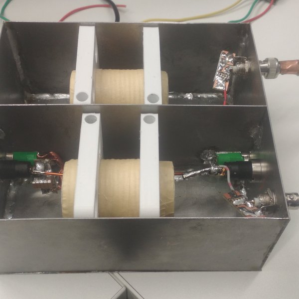
He put a 500uH inductor in the supply to the LED driver, which obviously totally messed up the LED driver as it went into input filter
instability. We'd have had to use an enormous input capacitor to work with such a big inductor. He said the need of the 500uH inductor
was to protect his RF amplifier during the conducted immunity tests. I thought they just needed an RF attenuator for that?
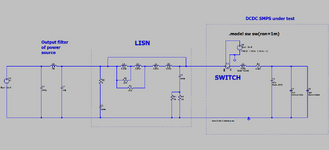
Also, its the case that most LISNs for this type of DCDC are actually putting a 5uH or 50uH inductor in the supply to the LED driver. Even this means
having to design the input filter with more capacitance than would otherwise be needed.
Why don't all the App Notes of these high switching frequency DCDC controllers tell about the fact that you wont be able to use a tiny MLCC
capacitor bank after all?...because it wont work with the LISN inductor.
I mean, in the application, our device will work on the output of a Meanwell or other Power Supply which has a very large output capacitor,
and causes no problems for our tiny MLCC input capacitor bank.....but due to the EMC testing, we have to re-design it to be able to work with the
LISN's output inductor
Is this not a failure of the EMC testing procedure?


