Nurahmed
Junior Member level 1

- Joined
- May 27, 2019
- Messages
- 19
- Helped
- 1
- Reputation
- 2
- Reaction score
- 1
- Trophy points
- 3
- Location
- Montreal, Canada
- Activity points
- 172
Hi,
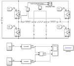
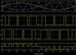
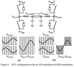
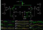
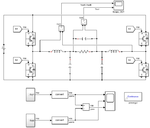
I am simulating this BTL configured H-Bridge inverter with BD modulation. When there is only a resistor load, the three-level PWM pattern is fine (VoutA-VoutB, resistor only). But after adding an LC filter, the PWM pattern is not correct (VoutA-VoutB, LC filter), the filtered sine wave is not correct too.
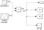
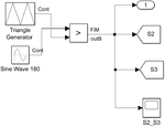
You can see the attached images for simulating schematics and waveforms. The LC filter value is calculated according to TI's filter design guide. I also tried setting initial conditions for L & C.
What could be the problem when adding the LC filter?
Thanks


