Continue to Site

Welcome to EDAboard.com

Welcome to our site! EDAboard.com is an international Electronics Discussion Forum focused on EDA software, circuits, schematics, books, theory, papers, asic, pld, 8051, DSP, Network, RF, Analog Design, PCB, Service Manuals... and a whole lot more! To participate you need to register. Registration is free. Click here to register now.

Dynamic Reconfiguration Port in Virtex 4 Transceivers.

Status
Not open for further replies.
I wasn't suggesting that the transceivers don't work at 4.2 line rate. My guess it has something to do with when you perform the reference clock frequency switch. That is why in one suggestion I made early you might want to try different reset sequencing. It seems to me that the transceiver may not be starting up correctly so can never synchronize to the input.

I am not sure whether PLL is getting locked to REFCLK. Looks like I need to check the RXLOCK parameter again for 4.2 gbps line rate. At present transceiver uses the reset sequence with RX Buffer. The state machine is designed in the current design is quite different from the FSM - GT11_RX.vhd of the rocket wrapper generated by the Core Generator but logic is the same.

This is the current reset sequencing fsm:
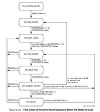
4485746900_1408821587_thumb.jpg


Should I test now by choosing transceiver to bypass the RX Buffer and use the below reset sequencing which puts RX_SYNC state.
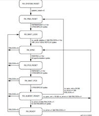
8350088100_1408821588_thumb.jpg


I once tried gt11_rx.vhd fsm with RX_SYNC reset sequence but didn't work. Maybe I can give another try with this reset sequence and look for the difference.

Never thought to ask but what is the protocol you are using for the links? Is it 8-bit data or 16-bit data, if you are using 16-bit data you should use two different K-codes for idle and alternate them. You should also make sure that the alignment never changes and that any insertion or deletion of symbols is done as pairs.
8B/10B encoding is not used. I will attach the transceiver configuration which I did below.
This is how the RX works in my design if I am not wrong since many parameters are just bypassed:
EVTh5.jpg

You know all these problems you are contending with is the reason Xilinx only used this version of transceiver in a single product. The V5 has a different transceiver that has a much simpler configuration, without all the extra options that the V4 transceivers had. Both V6 & V7 have continued that trend so they are all much easier to use.
I did not know this. Since I am coming across this transceiver for the first time, I have encountered so much with Virtex 4 now which should be documented from my side atleast !
 

Attachments

  • RocketIO_Wizard_Config.pdf
    328.6 KB · Views: 101
Last edited:

You aren't using any kind of encoding or are you doing the encoding outside the transceiver?

The way you have the transceiver setup looks like you're trying to use it like you would a pair of LVDS. I noticed it's set to use local reference clock so you absolutely have to oversample the input. If I recall correctly that mode is exclusively for running the symbol rate below the ~97.7MB raw symbol rate (no encoding, 32-bit at 3.125 Gbps).

As configured you have to perform some sort of external alignment as you aren't doing that using any kind of encoding as I can see. Also if your reference clocks aren't from an identical source then you will have issues with drift between your transmitter and receiver as you have the transceiver setup with a direct connection instead of using the internal FIFOs.

Have you ever worked with multi-gigabit transceivers before? What you are trying to implement is probably non-optimal and is probably more suitable for non-GT pins, if you don't plan on using any kind of symbol based transmission then you should probably use LVDS pairs and send your data and a clock over two pairs of pins. The whole point of using the transceivers is to send the data and transmission clock over the same pair of lines. You do that by embedding clock information into the data (8b10b encoding or 64b66b encoding). The encoding is to allow for enough transitions in the bits to perform clock recovery at the receiver. As there are more symbols allowed than possible data, special symbols called K-codes are defined which allow for synchronization and transmission of control information.

I'm not really sure why you went this route. You seem to be using the transceiver in a way that guarantees you will have problems with data synchronization, reference clock frequency drift. If this is for a product then you should stick with using an actual standard protocol of some sort that uses the transceivers built in resources that provide for synchronization and clock recovery instead of inventing your own method.

Regards
 

Status
Not open for further replies.

Part and Inventory Search

Welcome to EDABoard.com

Sponsor

Back
Top