thannara123
Advanced Member level 5

Hello ,
I am reffering some code from online written by Tahamid as follows
This is the code for generating sinewave to drive H bridge
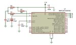
please see the circuit .
My question is the asked is written as comment in the above code which is in red colour.
RPOR0 = 0x1213; //RP0 - OC1, RP1 - OC2 //
In this piece code the RP0 and RP1 is mapped to OC1 and OC2 ,why dont maped RP2 and RP3 ?
NB : The new templete of edaboard is too much struggle to write a thread .Old was very simple ,I am disappointed .
I am reffering some code from online written by Tahamid as follows
Code:
const int sin_table[512] = { 0, 5, 10, 15, 20, 25, 29, 34, 39, 44, 49, 54, 59, 64, 68, 73, 78,
83, 88, 92, 97, 102, 107, 111, 116, 121, 125, 130, 135, 139, 144, 149, 153, 158, 162, 167, 171,
175, 180, 184, 189, 193, 197, 201, 206, 210, 214, 218, 222, 226, 230, 234, 238, 242, 246, 250,
254, 258, 261, 265, 269, 272, 276, 279, 283, 286, 290, 293, 296, 300, 303, 306, 309, 312, 315,
318, 321, 324, 327, 330, 333, 335, 338, 341, 343, 346, 348, 350, 353, 355, 357, 359, 362, 364,
366, 368, 370, 371, 373, 375, 377, 378, 380, 381, 383, 384, 386, 387, 388, 389, 390, 391, 392,
393, 394, 395, 396, 396, 397, 398, 398, 399, 399, 399, 400, 400, 400, 400, 400, 400, 400, 400,
400, 399, 399, 399, 398, 398, 397, 396, 396, 395, 394, 393, 392, 391, 390, 389, 388, 387, 386,
384, 383, 381, 380, 378, 377, 375, 373, 371, 370, 368, 366, 364, 362, 359, 357, 355, 353, 350,
348, 346, 343, 341, 338, 335, 333, 330, 327, 324, 321, 318, 315, 312, 309, 306, 303, 300, 296,
293, 290, 286, 283, 279, 276, 272, 269, 265, 261, 258, 254, 250, 246, 242, 238, 234, 230, 226,
222, 218, 214, 210, 206, 201, 197, 193, 189, 184, 180, 175, 171, 167, 162, 158, 153, 149, 144,
139, 135, 130, 125, 121, 116, 111, 107, 102, 97, 92, 88, 83, 78, 73, 68, 64, 59, 54, 49, 44, 39,
34, 29, 25, 20, 15, 10, 5, 0, 5, 10, 15, 20, 25, 29, 34, 39, 44, 49, 54, 59, 64, 68, 73, 78, 83,
88, 92, 97, 102, 107, 111, 116, 121, 125, 130, 135, 139, 144, 149, 153, 158, 162, 167, 171, 175,
180, 184, 189, 193, 197, 201, 206, 210, 214, 218, 222, 226, 230, 234, 238, 242, 246, 250, 254,
258, 261, 265, 269, 272, 276, 279, 283, 286, 290, 293, 296, 300, 303, 306, 309, 312, 315, 318,
321, 324, 327, 330, 333, 335, 338, 341, 343, 346, 348, 350, 353, 355, 357, 359, 362, 364, 366,
368, 370, 371, 373, 375, 377, 378, 380, 381, 383, 384, 386, 387, 388, 389, 390, 391, 392, 393,
394, 395, 396, 396, 397, 398, 398, 399, 399, 399, 400, 400, 400, 400, 400, 400, 400, 400, 400,
399, 399, 399, 398, 398, 397, 396, 396, 395, 394, 393, 392, 391, 390, 389, 388, 387, 386, 384,
383, 381, 380, 378, 377, 375, 373, 371, 370, 368, 366, 364, 362, 359, 357, 355, 353, 350, 348,
346, 343, 341, 338, 335, 333, 330, 327, 324, 321, 318, 315, 312, 309, 306, 303, 300, 296, 293,
290, 286, 283, 279, 276, 272, 269, 265, 261, 258, 254, 250, 246, 242, 238, 234, 230, 226, 222,
218, 214, 210, 206, 201, 197, 193, 189, 184, 180, 175, 171, 167, 162, 158, 153, 149, 144, 139,
135, 130, 125, 121, 116, 111, 107, 102, 97, 92, 88, 83, 78, 73, 68, 64, 59, 54, 49, 44, 39, 34,
29, 25, 20, 15, 10, 5 };

sbit MOSA at LATB2_bit;
sbit MOSC at LATB3_bit;
//D at LATB0_bit;
//B at LATB1_bit;

unsigned int Result;
int PWM_Scaling = 399; //25kHz
int Frequency = 131; //50Hz
unsigned int Phase;
int TBL_ID;

void T2Int() org 0x0022{ //Timer 2 overflow interrupt
Phase = Phase + Frequency;
Result = Phase >> 7;

TBL_ID = sin_table[Result];
if (Result < 256){    //A and D on
OC2RS = 0;
MOSC = 0;
OC1RS = TBL_ID;
MOSA = 1;
} else{ //B and C on
OC1RS = 0;
MOSA = 0;
OC2RS = TBL_ID;
MOSC = 1;
}
T2IF_bit = 0;
} void main()
{
LATB = 0;
TRISB = 0; //All PORTB output
ADPCFG = 0x3F; //All digital
PR2 = PWM_Scaling; //Set Frequency by setting Period Register //PR2 since I'll be using Timer 2

OC1CON = 0; //Disable compare module
OC1R = 0; //Initial duty cycle = 0
OC1RS = 0;
OC1CON = 0x0006; //Keep running in idle mode, Time base is TMR2,
                 //PWM mode with fault pin disabled
OC2CON = 0;
OC2R = 0; //Initial duty cycle = 0
OC2RS = 0;
OC2CON = 0x0006;
[COLOR=rgb(226, 80, 65)]RPOR0 = 0x1213; //RP0 - OC1, RP1 - OC2       // why this two  maped RP0,RP1 ,Not RP2,and RP3 ?[/COLOR]

SR = 0; //CPU priority interrupt level 0
T2IF_bit = 0; //Clear TMR2 interrupt flag
T2IP_2_bit = 1;
T2IP_1_bit = 1;
T2IP_0_bit = 1; //TMR2 interrupt priority 7
T2IE_bit = 1; //Enable TMR2 interrupt
T2CON = 0x8000; //TMR2 on, prescaler 1
while (1){ //Infinite loop – Nothing to do now
}

} //End of code
This is the code for generating sinewave to drive H bridge
please see the circuit .
My question is the asked is written as comment in the above code which is in red colour.
RPOR0 = 0x1213; //RP0 - OC1, RP1 - OC2 //
In this piece code the RP0 and RP1 is mapped to OC1 and OC2 ,why dont maped RP2 and RP3 ?
NB : The new templete of edaboard is too much struggle to write a thread .Old was very simple ,I am disappointed .
Attachments
Last edited by a moderator: