Continue to Site

Welcome to EDAboard.com

Welcome to our site! EDAboard.com is an international Electronics Discussion Forum focused on EDA software, circuits, schematics, books, theory, papers, asic, pld, 8051, DSP, Network, RF, Analog Design, PCB, Service Manuals... and a whole lot more! To participate you need to register. Registration is free. Click here to register now.

Driving MOSFET with 5V PWM for 12V fan speed control

Status
Not open for further replies.

alipoor90

Junior Member level 2
Joined
Jan 3, 2013
Messages
21
Helped
0
Reputation
0
Reaction score
0
Trophy points
1,281
Activity points
1,435
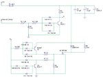
I came up with this circuit to control a 12V 6A fan's speed by a 5V PWM from another circuit, not sure if it's gonna work (i'm not very experienced nor knowledgeable in electronics), and i have a few questions:

1- to compensate for Q1's Vce, and turn off Q4 completely and reliably, when Q1 in on and A is low, i added one extra diode in series with Q4's base (total 2), is this a good idea? is it necessary as i thought?

2- are D4, D5 and D12 necessary in this circuit? (i put them there as part of baker clamp for each transistor, to charge/discharge the base faster when switching)

3- is there anything else that you think is unnecessary/lacking/wrong?


IMG_20190103_031031_763.jpg


Thanks
 
Last edited:

A logic level FET or a eGaN device could be direct driven
from the "5V PWM output" if it's strong enough, or a gang
of paralled 5V CMOS inverters might do for a current boost
(octal bus transceivers with 24mA drivers (@vol) are pretty
stout).

Using a low side switch was a good idea for simplicity but more
simplicity (at least, from a parts count standpoint) can be
had (presuming you're in a country where you can get IC
components freely).
 
Presumed you want to use a MOSFET that requires > 5V Vgs to be fully turned on, some kind of gate driver with level translation will be necessary. The present circuit, besides being overly complex, doesn't work however. You'll find that Q2 never turns off due to node A being clamped to about 1V by D9 and Q4. A complementary emitter follower would be a more appropriate solution.

Another point to consider, if the fan uses an electronically commutated motor, it's most likely equipped with a large input capacitor and not suited for PWM operation without an external inductor.
 
Hi,

There are dedicated "Mosfet gate driver ICs".

Klaus
 
Hi,

There are dedicated "Mosfet gate driver ICs".

Klaus


Hi, i'm aware of that but i wanted to do this as an "exercise" :)

- - - Updated - - -

Presumed you want to use a MOSFET that requires > 5V Vgs to be fully turned on, some kind of gate driver with level translation will be necessary. The present circuit, besides being overly complex, doesn't work however. You'll find that Q2 never turns off due to node A being clamped to about 1V by D9 and Q4. A complementary emitter follower would be a more appropriate solution.

Another point to consider, if the fan uses an electronically commutated motor, it's most likely equipped with a large input capacitor and not suited for PWM operation without an external inductor.


would a resistor before baker clamp diodes of the Q4 fix the problem?
 

I guess not, because R1 doesn't pull node A high enough. Why not use a simulator (e.g. Ltspice) to check the circuit behavior?

As said, there are circuit alternatives that provide the intended function with less effort.
 
1) Agree: don't re-create the gate driver functionality. Many single chip solutions exist for this that will be better in every way.

2) I don't see any problem finding a suitable 'logic level' fet capable of switching 12V/6A with a 5V gate drive directly. On first thought this would be my preferred solution if I already had a 5V pwm signal.
 
Hi, i'm aware of that but i wanted to do this as an "exercise" :)

- - - Updated - - -


This is very valuable if you want to learn to design electronic circuits. I've been doing the same for years and I gained a lot of experience.
I even built some cirucits from scratch even though there were ready solutions. The thing I noticed is that there are many electronics "engineers" that don't know the fundamentals of electronic design even though they graduated from technical universities. The only way to become familiar with electronic design is to practise. At the beginning your circuits may not work at all or work improperly; they also get too complex but as you progress they will get smarter. So grab the soldering iron and go !
 
Status
Not open for further replies.

Part and Inventory Search

Welcome to EDABoard.com

Sponsor

Back
Top