Continue to Site

Welcome to EDAboard.com

Welcome to our site! EDAboard.com is an international Electronics Discussion Forum focused on EDA software, circuits, schematics, books, theory, papers, asic, pld, 8051, DSP, Network, RF, Analog Design, PCB, Service Manuals... and a whole lot more! To participate you need to register. Registration is free. Click here to register now.

Driving 140x 3W LEDs

Status
Not open for further replies.

Xenobius

Member level 5
Member level 5
Joined
Feb 25, 2019
Messages
84
Helped
0
Reputation
0
Reaction score
0
Trophy points
6
Activity points
850
Hi, this is a question about driving 140x LEDs which are rated from 3.2 to 3.6v and upto 700mA current (link for them here)

My design: I was thinking of using 24v to power 7x in series bringing the voltage down to 3.43v on each LED and I think this is fine.

My application: This is a Dual Sided PCB exposure box complete with vacuum. So there will be 70 leds on each side. And I might switch on the bottom, the top or both at any time. Also based on assumption and on other projects I found, with that much power it might take a maximum of 30 seconds to expose a full board.

My questions:
  1. Is it correct that I will need 45.5AMP per side to drive 70x @ 650mA? I mean the math is correct but is there a better way to drive an LED?
  2. With regards to limiting the current, I am only familiar with putting a resistor in series... is there a better way for example limit the current for all 7 leds in series in such a way that I do not waste so much power in heat?

How would you do this assuming that you need 70x leds on each side? I am happy to wait 1 minute to be fair instead of 30 seconds but again I cannot know until I try. I may be wrong and will need 2 minutes who knows.

Thanks for reading
 

My design: I was thinking of using 24v to power 7x in series bringing the voltage down to 3.43v on each LED and I think this is fine.
Don't set the voltage and assume the current will be correct, you need to provide a controlled current source, not a voltage source.
You need a properly designed SMPS to do this, I would forget any notion of series resistor when the load is 420W. I would also consider using a much higher voltage and more LEDs in series because high voltage is much easier to work with than high current.

What kind of LEDs are you using? If this is a photo resist exposure box you really need suitable UV LEDs and you probably don't need anywhere near as much power. 3W short wavelength UV LEDs are VERY expensive!

Brian.
 
State of the art for LED lighting is constant current switch mode supply.

Parallel connection of LED strings is only suggested if the forward voltage is guaranteed to keep certain limits, e.g. with LEDs binned by the manufacturer. Otherwise series resistors for current balancing should be used.
 

So the LEDs are 3W, 370nm UV light they will cost around 100eur within budget for this project. I've been using florescent tubes for 19 years now and I cannot find the ones I used so its time for an upgrade.

@betwixt - I like your idea of using higher voltage and will do just that using switch mode power supplies. I might use 2 one for each side to keep them small too. However the current limiting is still a question.
@fvm - I dont get the part where you said "binned by the manufacturer" are you saying that the leds might not be identical and if put in series this is a problem? or did you mean something else?

What about the part where you mentioned parallel connection? I was originally thinking of having 7x leds in series with 10x rows in parallel connected to 24v (now I will change this with higher voltage) however what did I miss?

Thanks guys for your time
 

What you missed was that LEDs are essentially constant voltage devices. It means the voltage across them will TRY to stay constant regardless of the current that flows through them. However, in maintaining the voltage, they can easily dissipate far too much power and burn out. For example, if the LED sustained 3.5V across it, think what would happen if you applied 4V, in attempting to drag the 4V down it would draw as much current as possible and either the PSU or LED would go pop.

The other problem, which is why FvM mentions binning is that the forward voltage is not precisely specified. In fact with LEDs it is common for their forward voltage to vary by as much as 10%. So if you connect them in parallel, either individually or in strings, the total forward voltages may not match. When you apply power, the string or LED with lowest Vf will conduct more than one needing higher voltage. This is a problem that gets worse as more LEDs are joined in series as their total forward voltages are added to together to get the overall string voltage. Binning is a process where the manufacturer sorts the LEDs into different Vf 'bins' during their testing process so you can buy them with some confidence they are the same but there will still be some variation even within a single bin.

The solution is to use constant current to drive the LED strings. In a series circuit, the same current flows through all the LEDs but the voltage across each LED can still be slightly different. It means the total string voltage may be slightly higher or lower than predicted but that doesn't matter because a constant current source adapts its voltage to compensate. Ideally, you would use a constant current source on each string but you can 'cheat' a little if you still use a constant current source but add a small resistance in each of the parallel paths. The resistor will to some degree balance the current by preventing one string hogging all the current from the others. It isn't an ideal solution but it may be cost effective.

Maintaining constant current isn't difficult, the classic solution is to add a small resistance (maybe a fraction of an Ohm) in the ground return wire of the LED wiring, Ohms Law tells us the voltage dropped across the resistance will be proportional to the current flowing through it so all we have to do is control the supply voltage so the voltage across that sense resistor stays constant. Constant drop = constant current.

Brian.
 
All of a sudden this is getting a bit complex for my knowledge. I will try to make sense of this when I am more quiet and will post my findings. Thank you for the moment.
 

How will you cool each LED? 3W is a lot of heat in that tiny LED. Since it is Chinese no-name-brand then a suitable heatsink might be difficult to find.
 

Yeah 3W you might be right. I was thinking an A4 sized PCB with 10x rows of 7 leds spaced 3cm apart and "assuming" the PCB would be enough for 45 seconds... I saw someone who used a 2 part heat transfer compound which basically dries and hardens and is used to "stick" the leds with it. Then he simply wired the LED without a board. He used aluminum strips however the LEDs were 1W...

hmm I need a better design

- - - Updated - - -

So as an alternative design I am now considering mounting the LEDs on Heatsinks directly (with their own PCB) rather then my own pcb like so. Heatsink Link and LEDs 3W 380 to 385nm What do you think? Also really cheap LED bases that can be used directly on the heatsink

- - - Updated - - -

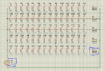
So would the values in blue make sense along with the following power supply? Circuit.PNG Power supply 480W (for 2 of these circuits)
 
Last edited:

I do not know how you can mount 4 LEDs to the 12W heatsink you found. A glue that passes heat?

Since the LEDs are cheap Chinese no-name-brand then their forward voltage are not binned. Then some will be 3.2V and maybe others will be 3.6V.
If you connect 14 LEDs in series and they all have a 3.2V forward voltage then they need 3.2V x 14= 44.8V. The 5.6 ohm resistor will produce a power of only 1.8W (then why is it rated at 30W??) and the LEDs will have a current of 0.57A and produce a power of 1.8W each.
If all 14 LEDs are 3.6V then they need 3.6V x 14= 50.4V and might produce no light or only very dim light when powered from 48V.
 

Hello Audioguru, Yes Arctic silver has this product which you can mix and it hardens. In fact you can even find another solution by arctic silver that helps remove it once it hardens link here too.

As for the LEDs not being binned I'm just going to have to try. My reasoning was that I will split 48v amongst 14 leds and that should leave them with 3.42857V each which is within the range specified. I was then reasoning that if the recommended current is between 600 and 700mA, then with a 5.6ohm resistor it will allow around 607mA to pass. Its 30W because 48v x .607A is 29.136W

I know the LEDs are rated at 3W however 3.42v x .607A = 2.08W. I don't quite understand where you got the 1.8W from I am clearly confused :)
Thanks for your help.
 

Hi,

As for the LEDs not being binned I'm just going to have to try. My reasoning was that I will split 48v amongst 14 leds and that should leave them with 3.42857V each which is within the range specified. I was then reasoning that if the recommended current is between 600 and 700mA, then with a 5.6ohm resistor it will allow around 607mA to pass

You didn't understand yet.
You still think in "voltage" when driving a LED.

Connect a fixed voltage to a LED:
* it may be OFF
* it may be dim
* it may be bright as expected
* it may be overly bright
* it may be killed

Connect a fixed current to the LED
* and you will get the desired brightness

If you don't accept this your project likely will fail.


3.2V ... 3.6V is the range of voltage for 700mA. What voltage they need for 600mA is not specified....but it will be almost the same.
Worst cases are:
* 14 * 3.2V = 44.8V .... leaves 3.2V across the 5.6 Ohms giving a current of 570mA
* 14 * 3.42857V = 48V ... leaves no 0V for the resistor ... the LEDs will be OFF
* 14 * 3.6V = 50.4V ... the LEDs will be OFF.

And you need to consider wiring resistance:
* 1Ohms wiring resistance per string will drop brightness by about 15%

You need to consider varying power supply output voltage.
It will vary:
* from supply to supply
* with time
* with load
* with temperature
...
If you just calculate with +/-2.5% of variation, this is 5% in total, or 2.4V in total ... resulting in about 400mA of current variation.

Klaus

Added:
If you buy that cheap LEDs ... you need to expect an untypical distribution of the forward voltages.
It's not very unlikely that they sell the rest of LEDs after the binning. If so, then you will not find LEDs with a forward voltage of - let's say - 3.3V up to 3.5V. You may just get LEDs with a forward voltag below 3.3V or above 3.5V. All the other "good" LEDs are sold for their regular price.
 
Another point to note when considering the heat sinking is the center back side of those LEDs is a metal slug. It is designed to be soldered to the heatsink to maximize heat transfer and importantly, it is electrically bonded to one of the legs. You can (I've done it successfully) use heat conductive paste but you have to be certain there is no unintended electrical connection.

Brian.
 

@Klaus - Hmm this is really interesting. I knew common LEDs worked with current but I assumed these were different. What I didn't realise was that they will drop different voltages across which will affect the voltage across the resistor. Thanks for the explanation.
@Betw - So those little LED bases that I posed are made of aluminum. My intention was to solder the LED on top of those aluminum bases (with a little drop of common thermal paste) and then stick the aluminum base on a bigger aluminum block using the sticky-2-part-thermal-paste. I was going to solder wires directly onto the aluminum base.

So the verdict is that with an unreliable source of LEDs or a super expensive LEDs I might as well scrap everything...
 

Added:
If you buy that cheap LEDs ... you need to expect an untypical distribution of the forward voltages.
It's not very unlikely that they sell the rest of LEDs after the binning. If so, then you will not find LEDs with a forward voltage of - let's say - 3.3V up to 3.5V. You may just get LEDs with a forward voltag below 3.3V or above 3.5V.

So what? The usual design is to connect them in series, supply with constant current driver and your're done. You don't need to care about the spread in forward voltages.
 
Some of the very cheap LEDs will be shorted and with your simple circuit using a resistor to limit the current then the current will be too high and cause the good LEDs in series to quickly burn out.
Or some of the very cheap LEDs will not conduct and cause the entire string of LEDs to be always be turned off.
How long will very cheap LEDs work or how soon will they fail? In a few days or in a week?
 

So would you say a constant current circuit would solve the problem of cheap leds?
Ie: A circuit which allows 650mA to pass through to 7 or 14 LEDs in series?

- - - Updated - - -

The aluminum bases have solder pads
 

What is the objection if you put 70 LEDs in series and drive by a single transistor constant current running from the rectified AC?

Why not mount them on a regular double side PCB with reasonable spacing (as desired)?

Paint the solder side of the board with some black paint and use a small fan.

LED matching is needed only if you are going to use them in parallel.

Total power dissipation will be 140x3=420W plus power supply and series resistor losses. It may not be much if your box is 40cmX40cmX30cm.

If you have only a voltage supply (24V), you can put 7 LED in series+series balancing resistor - ten such sets in parallel.

When you put them in series, you do not bother about the forward drops (variations) - even if you are driving with a const voltage supply.

Put a aluminium foil punched with the LED emitter size holes, on the final board to reflect UV to the sample.
 
Status
Not open for further replies.

Part and Inventory Search

Welcome to EDABoard.com

Sponsor

Back
Top