Continue to Site

Welcome to EDAboard.com

Welcome to our site! EDAboard.com is an international Electronics Discussion Forum focused on EDA software, circuits, schematics, books, theory, papers, asic, pld, 8051, DSP, Network, RF, Analog Design, PCB, Service Manuals... and a whole lot more! To participate you need to register. Registration is free. Click here to register now.

[SOLVED] Driver IC ULN 2003 working

Status
Not open for further replies.

tnnazar

Junior Member level 1
Joined
Mar 4, 2011
Messages
18
Helped
1
Reputation
2
Reaction score
1
Trophy points
1,283
Location
Sharjah - U.A.E
Activity points
1,394
I am new to this forum... A microproccessor , a uln 2003 ic and relays were used in a control panel to operate ac 220v motor,flasher... how uln operate the relay.. Here, need 12v dc to activate the relay ..can anyone explain it ..
 
The 12 V relay goes between the open collector output and the 12 V supply. Remember the reverse bias diode to take care of the relay back EMF
 
that DC voltage is given directly from power supply or from regulator output...

It depends on the relay you use,....

Thank u sir
can u pls explain this also .
i have circuit like this... first control signals are given from many devices to optocouplers ..Then it is given to micro processor ... the mp gives signal to ULN 2003 .. ULN drives 2 relay... From relay its clear for me...

I just want to know how ULN 2003 operates..

---------- Post added at 22:29 ---------- Previous post was at 22:28 ----------

Thanks for ur reply..
 

hi
u can see this, i think it may help
**broken link removed**
===================================================
this is an Example:
**broken link removed**
===========================================================
you can get them from here
ULN2003.pngULN2003 internal picture.PNG
 
Last edited:
ULN2003_stage.jpeg

This is the internal circuit of ULN2003, it has seven of these, one for each output stage.

It has 2 transistors connected in Darlington configuration to multiply the current gain.
The output transition is an open collector, this means that it can either leave the output floating of it can sink current (provide ground).

What you do with this kind of circuit is to connect your load to the positive supply and the other side to the output of the ULN2003, when the input of ULN gets a positive voltage it connects the output load to the ground and current can flow through the load, when the input of ULN is 0 then the output is left in a high impedance state (floating) and no current can flow through the load.

This is a picture of a ULN2003 driving 7 relays
ULN2003_relay.jpg

Alex
 
Have a look at attached pdf file.

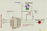
Here the micro-controller is controlling 4 relays via ULN2x03.
Note how one end of relay coil is tied to the ULN2x03 pin and other to +V.
For ULN2x03, operating via mcu is very easy, the logic is simple, ULN2x03 is a sink driver, what you need to do is make the PIN HIGH that goes to ULN's corresponding IN.
e.g you have 6 relays connected to ULN, PORTB RB0:RB6 of PIC16F877A is connected to the ULN.
Now you have to turn relay one at a time the sequence could be like:
CASE 1:
RB0=1
RB1=0
RB2=0
RB3=0
RB4=0
RB5=0
RB6=0
CASE2:
RB0=0
RB1=1
RB2=0
RB3=0
RB4=0
RB5=0
RB6=0
CASE3......

Although the code will work this way as well, but for all practical purposes, it will have to be optimized.
 

Attachments

  • Schematic Prints.pdf
    34 KB · Views: 284
i have a question here, how about the voltage input maximal that this IC can be accepted?
 

Status
Not open for further replies.

Similar threads

Part and Inventory Search

Welcome to EDABoard.com

Sponsor

Back
Top