Continue to Site

Welcome to EDAboard.com

Welcome to our site! EDAboard.com is an international Electronics Discussion Forum focused on EDA software, circuits, schematics, books, theory, papers, asic, pld, 8051, DSP, Network, RF, Analog Design, PCB, Service Manuals... and a whole lot more! To participate you need to register. Registration is free. Click here to register now.

Driven Right Leg circuit

Status
Not open for further replies.

luckyvictor

Member level 4
Member level 4
Joined
Dec 1, 2009
Messages
78
Helped
0
Reputation
0
Reaction score
0
Trophy points
1,286
Activity points
1,903
Here is a picture of a part of a circuit, which contains a right leg driver.

My understanding of DRL is a circuit which send a signal to a human body, therefore this human body would have the same 'common voltage' as the circuit, which helps to increase CMRR.

However, I would like to know how the below DRL works, especially at the point A, B and C.

Also I have seen quite a few of DRL circuits, and they all do some sort of filtering (Low pass filter), I would like to know what value of cut off freq is aiming actually.
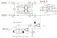
 

As far as I can see (and I may be wrong) point A is simply a buffered version of the average common mode signal from the terminals.

IC201B is an inverting integrator. It has a gain which decreases with increasing frequency. One way to look at it is when the frequency is low the capacitor is a high reactance so the gain is high. At very high frequencies the capacitor will be a very low reactance so the amplifier will have almost no output.

An integrator like that would just charge C216 until it hit the power rails but the feedback through the leg and the terminals provides a negative feedback path so it should stabilise at the voltage set by the pot P201.

I assume C212 and R213 are to isolate some of the capacitance from the opamp to ensure it is stable, but I am not certain. Opamps don't usually like large capacitive loads so without R213 it could be unstable.

Keith.
 

Thank you for your reply. I agree with all your points, without R213 and C212 it simply looks like an integrator.
 

Status
Not open for further replies.

Similar threads

Part and Inventory Search

Welcome to EDABoard.com

Sponsor

Back
Top