gres
Full Member level 4

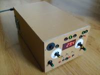
Some systems need a few power source, or even negative voltage. Single feeder even with additional +5 and +12V is not enough.
Projects: few times modify so now i thing they're fine
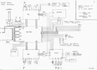
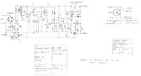
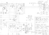

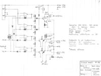
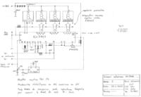
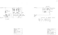
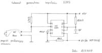
As you can see, power supplyes are similar to projects from electronics-lab.com. Importand change is that 11N4007 diode is replace with BYW98100. It protect feeder, when it's current limiter start in symmetric mode, when power supply work in single mode 0-60V.
After diagrams, i design boards ( manually). I already had boards for feedders after single channel power supply.
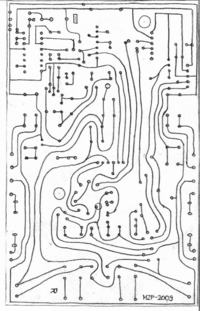
Here's view of MZP-2009 module paths
When I knew boards dimensions I started to design casing..
Here's pictures in 1:1 scale.
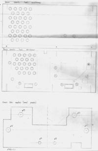
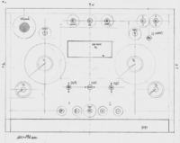
Boards are made by chlorinated- rubber pen, etching in B327 solution.
Feeder is build on 12mm pine board covered by 3mm layer of walnut tree. Rest walls are made by floor panels 6mm thin. Firstly i made front panel and chassis with potentiometers.
Back side of feeder consist air tunnel with radiators and ventilators. Ventilators mounts are made up with wire from old umbrella
Summary length of all cable connections is 25m!
I made scale of current limit. It wasn't very easy. Firstly I put paper circle on potentiometer axle and in experimental way placed scale. Than expend scale 200%. At new paper sheet make the same circle, with double radius and mark scale as on big circle. Marks draw by felt-tip and then diminish scale 50%. Glass comes from cd cover.
At front panel we have power button. 3 diodes - transistor's temperature. Green one means that thermostat is on, red - temperature higher than 90oC. In the middle of panel is voltmeter with buttons - symmetric / double mode, channel voltage (1 or 2), outputs on/off. Knobs are responsible for set current limit, and voltage.
Both power supplies consists voltage regulation from 0 to 30V and current limit 10mA to 4A. They can work in :
- double mode
- symmetric
- parallel
More information : https://www.elektroda.pl/rtvforum/topic1530816.html
