Vermes
Advanced Member level 4

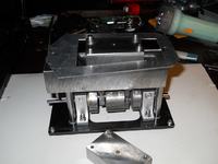
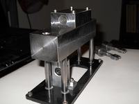
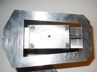
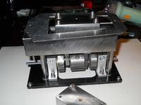
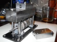
The motor was projected in Inventor, then drawn in AutoCad and finally made in real.
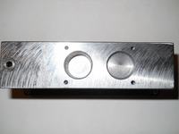
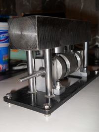
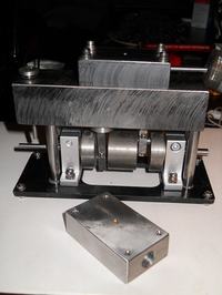
The steam engine is built of tool steel. Only cranks of the shaft were cut from ST steel and plate conveying the position of the roller setting on the timing plunger is made of aluminum alloy. Parts of the machine were made in different techniques: rolled shafts, the base was laser cut, drilled holes and handjob with grinder and taps.
The shaft was the most problematic - it can't have beating because of the bevel gears (gear angle). The shaft was built of 3 steel discs. The discs handling the cranks are screwed across and additionally glued. Axle of the shaft in order to maintain centric, was set up as a unit and, after twisting, the unnecessary sections were cut away.
The desired effect was half succeeded in achieving, since the right side of the shaft has a slight beating (but it would not be used).
The motor has very little friction and seizure. The shaft begins to spin after blasting in the power hole. After lubricating, there shouldn't be any problems with booting.
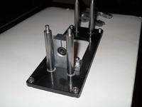
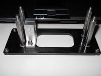
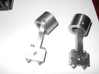
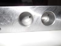
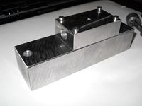
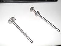
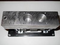
Link to original thread (video) – Maszyna parowa dwutłokowa z rozrządem suwakowym