Continue to Site

Double balanced mixer transformer replacing

Status
Not open for further replies.

neazoi

Advanced Member level 6
Joined
Jan 5, 2008
Messages
4,161
Helped
13
Reputation
26
Reaction score
15
Trophy points
1,318
Location
Greece
Activity points
37,227
Hello,
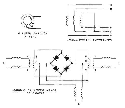
I have seen this double balanced mixer design, which uses ft50-61 for the T1.
I would like to improve the thermal stability of it by using T50-6.
Using toroids calculator I found that 7 turns on a FT50-61 are 3.38uH.
On he other hand 3.38uH on a T50-6 will require 29 turns.

I have two things that worry me in substituting these transformers:

1. I calculated the inductances assumming a single wire. T1 is trifilar. Will the inductances be the same for each wire?

2. Should I worry about achieving the same inductance, or should I just achieve the same turns ratio instead? I.e is is right what I am doing here?
 

Attachments

  • mix.png
    mix.png
    19.3 KB · Views: 201

1. Yes
2. turns ratio matching is the most important unless you want to throw away gain or you have an excessive LO level. The inductance should be sufficient for the working frequency. i.e. Xl> 5 X working impedance.
Frank
 

1. Yes
2. turns ratio matching is the most important unless you want to throw away gain or you have an excessive LO level. The inductance should be sufficient for the working frequency. i.e. Xl> 5 X working impedance.
Frank

So could I substitute the two transformers by just calculating the primary/secondary inductances? would the ratio be kept roughly the same, or do I need to do other calculations?
 

You have not mentioned the frequency range you are dealing with. 40 years ago I used to use wide band ferrite transformers as part of the input circuitry for wide band communications kit (50KHZ - 30MHZ), We knew that 1/2 a turn was good for a 50 ohm circuit right down to 50 KHZ and then just designed on turns ratios. We did have marginal leakage inductance problems at 30 MHZ, causing losses of about .3 Db. We used about 0 DBm LO into 200 ohms to switch our mixer diodes - gave excellent linearity. Can't remember the gain distribution but it had a usable 120 DB dynamic range.
Frank

The lower oscillator in the schematic runs at 17mhz and the upper at different frequencies on HF, mixed together to produce an analogue synthesizer. The transformer is trifilar (unbalanced to balanced, phasing) to drive the diodes.
I guess I do not have to take care about ratios, in that case but only take care about impedance, since all turns are wound together?
 

Hi Neazoi,

I'm no expert, but have studied the subject a fair amount. The thing is, the number of turns is a compromise; you don't want too many, because it affects the high frequency performance (ferrite will look like an air core at high freqs, so really you're not considering the ferrite at high frequencies. And by high frequency I mean even in the low tens of MHz).. You don't want too low a number, because then the low freq response is compromised. So, from gut instinct, the number you mention (29 turns) sounds too much for HF. Hopefully others with practical experience can suggest if it sounds reasonable or not. It might be ok, but if not, you need to reduce the number of turns. What Chuckey said sounds about right, and I'm guessing it was with a ferrite with a reasonably high 'AL' value. Note that the impedance of the transformer will be unaffected, since that just depends on the 'characteristic impedance' of the transmission line (it is affected a bit by the toroid, but by a very small amount).
Also, if you try to find more info on this on the web like I did, you'll find there is a lot of conflicting (and some plain wrong) information.

---------- Post added at 16:35 ---------- Previous post was at 16:28 ----------

Also, I just say your mixer design image. Btw, apparently such diode mixers are quite tricky to design (it will work, but perhaps not optimally), however you could consider a FET design, i.e. a quad fet passive mixer design which give better performance but need quite high drive power. There is not much literature on it these days, because the gilbert cell design got so popular (because it was easier to put on an IC because it did not need transformers). I'm very interested in fet mixers, but again I wouln't consider myself an expert in this area so I don't want to advise too much..
 

Nevertheless a well designed diode mixer should exhibit excellent noise performance. It is tricky to design indeed, it needs careful matching of the diodes, using schotcky diodes and careful winding of transformers. maybe a prepackaged minicircuits mixer would be a better solution...at least with known characteristics,but I am unaware of their phase noise, even in these hich level mixers like sbl-1h
 

A doc which has lots of good tips is called "sources of intermodulation in diode-ring mixers" by H.P.Walker. To summarize it, he mentions that distortion occurs because of diode non-linearity, and diode switching time. The non-linearity can be reduced by sticking low-value resistors in series with each diode, but then there is some additional loss. Diode switching time is reduced by using a square wave LO instead of sinewave (or have a very large sinewave). Also the paper suggests tips to keep it all balanced - matched diodes as you say (and matched resistors), and also using baluns on each end (i.e. each one feeding the transformers in your diagram, so that for example on the left side of the diagram, not to connect to ground and the capacitor as shown, but to connect to a bifilar wound transformer, and the input end of the transformer would then be connected to the capacitor and to ground) and also to ensure tightly twisted wire in the toroids. I think with a combination of this, and good diode matching, you may get better results than an off-the-shelf product.
 

I was not able to find this document you refer, it would be helpful If I had a copy, especially to see how these resistors in the diode section are connected.
Generally high level mixing is better in terms of noise but the oscillators could be quite tricky to make.
The balun you refer to is to preserve balance. I have seen it in a spectrum analyzer project and I attach such a mixer here
 

Status
Not open for further replies.

Part and Inventory Search

Welcome to EDABoard.com

Sponsor

Back
Top