Continue to Site

Welcome to EDAboard.com

Welcome to our site! EDAboard.com is an international Electronics Discussion Forum focused on EDA software, circuits, schematics, books, theory, papers, asic, pld, 8051, DSP, Network, RF, Analog Design, PCB, Service Manuals... and a whole lot more! To participate you need to register. Registration is free. Click here to register now.

Doppler "radar" motion detector design

Status
Not open for further replies.

harvie

Full Member level 1
Full Member level 1
Joined
Sep 10, 2014
Messages
98
Helped
2
Reputation
4
Reaction score
2
Trophy points
1,288
Location
Prague
Activity points
2,486
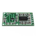
In recent years i've noticed rise of extremely cheap motion detectors based on doppler effect in RF domain. There are lots of them, one example looks like this:
s-l300.jpg

To my knowledge there are 3 main blocks to it:

* some black magic RF PCB design
* single transistor with few passives working as TX oscillator and RX mixer at the same time
* some generic PIR motion detecting IC repurposed to work with RF instead of PIR (provides monostable latching and clean output to drive external circuitry). It's very suprising, but it seems that the IC doesn't really execute any doppler detection, it just provides nice long pulse once it's triggered by the RF frontend.

I would like to implement this myself, given that i don't have pretty much any RF design experience.
I want to only take the RF block with PCB and transistor and couple it directly to Arduino or ESP32 input to handle the latching, so i can reduce part count and easily tune the sensitivity in my firmware. I need to shrink this circuit to minimal size, which should be possible, given the fact that only half of the PCB does actual job and rest is there just for convenience.

Do you think this is possible? Given that i will COPY the existing RF PCB design and only replace the logic with my own uC. Also i might want to slightly modify the PCB design to tune it for thicker 1.6mm FR4 board.

Let's say i want to design my own arduino board on 1.6mm FR4 with doppler motion sensor without the intermediate PIR IC. Maybe replace the PIR IC with schmitt trigger or opamp and handle output by arduino interrupt. So i can trigger the motion detected if i get N pulses per second (where N is tunable according to desired sensitivity)


Any ideas where should i begin?
 

Output of the motion detector RF front end is an analog signal as delivered by the mixer circuit. It can be best processed by an µC ADC input. For direction sensitivity, you need a quadrature mixer frontend with two outputs, by the way.
 

Output of the motion detector RF front end is an analog signal as delivered by the mixer circuit. It can be best processed by an µC ADC input. For direction sensitivity, you need a quadrature mixer frontend with two outputs, by the way.

Cool. Thanks for info. I was worried if the output analog signal has enough amplitude (voltage) to be detected by internal ADCs of common uC (eg. atmega).
I don't need direction sensitivity, but it surely might be nice feature for other projects. I guess you can even measure speed of motion if needed.

But actually all i need is LCD screen to turn off when there's nobody around for a while (to save energy). But i can't use (P)IR detector, because of physical design of enclosure. Also doppler detector looks very sexy and cheap to manufacture.

I guess i will start probing some existing module with scope and slowly remove unnecessary components one by one. I am not sure about PCB design... Should i bootleg existing PCB from different manufacturer or is it possible to design such PCB with some rules of thumb and simple calculations when i have no experience? I use kicad and it has some very basic calculators for RF aspects of PCBs, but i've never really used that. Obviously i would preffer to learn how to design such PCB myself, but i don't have year to learn all the theory needed. OTOH i am not afraid of experimenting and failing several times, since i can mill my own prototype boards within hour or so :)
 

To my knowledge there are 3 main blocks to it:

I guess the antenna is the left side PCB trace: do you have any idea about the frequency of operation? The transistor is the oscillator and mixer?

I am just curious.
 

I guess the antenna is the left side PCB trace: do you have any idea about the frequency of operation? The transistor is the oscillator and mixer?
I am just curious.

Yes. Antenna is left side. It's double sided and usualy has some funny shape. IIRC this one has some kind of circle on the other side.

These modules usualy range between 2 to 30 GHz, depending on what you buy.

There is some advanced RF magic that i don't fully understand. But there is only single transistor, you can see it on photo. It has to oscillate to feed the antenna with RF signal, when it's later reflected back to antenna from moving object it has slight frequency shift caused by doppler effect. This is then (maybe amplified in the same transistor???) and mixed back with original oscillator signal (similar to heterodyne FM receiver). Demodulated signal then contains only the "baseband" of doppler shift without any RF offset, which makes it suitable for further processing and motion detection (obviously this signal is present only when there is some moving object near the antenna)
 

Yes. Antenna is left side. It's double sided and usualy has some funny shape. IIRC this one has some kind of circle on the other side.

Very interesting. And the IC does all the donkey work? I see lots of connections to the ground plane. What are the outputs you get from the IC? Can you get the velocity too?
 

These things work by splitting the output of a UHF/Microwave oscillator into two paths. The majority of the signal is radiated by the on-board antenna, a small amount is fed to a mixer. Signals reflected back to the antenna are also sent to the mixer. The mixer produces an LF signal consisting of the difference between Fosc and the reflected signal. If there is no movement in the near vicinity the signals will be the same frequency but due to the extra distance traveled along the reflected path there might be a phase shift between them. The phase shift produces a steady DC voltage from the mixer.

When something nearby moves, the phase and frequency (Doppler shift) of the reflected signal will change and instead of DC leaving the mixer, it will be a frequency which is proportional to the rate of movement. Typically it will only be a few Hz so the following amplifier stage (the IC) is a low pass filter and high gain amplifier to raise it to a more usable voltage. Some modules also incorporate a comparator so it can compare the rate of movement with a pre-set level, for example to operate an automatic door when someone approaches it.

Brian.
 
These things work by splitting the output of a UHF/Microwave oscillator into two paths. The majority of the signal is radiated by the on-board antenna, a small amount is fed to a mixer. Signals reflected back to the antenna are also sent to the mixer. The mixer produces an LF signal consisting of the difference between Fosc and the reflected signal. If there is no movement in the near vicinity the signals will be the same frequency but due to the extra distance traveled along the reflected path there might be a phase shift between them. The phase shift produces a steady DC voltage from the mixer.

Basically a micro version of the million dollar defence equipment! Thanks for the details.
 

And the "CDS" appears to be an LDR for suppressing operation in daylight, which further reinforces the idea that the IC is from a PIR sensor application.

Brian.
 

It seems to explain everything.

A nice thing to play around. Does it go through the wall? RF should be able to pass through the door and walls (but I do not know about the reflected beam)...
 

harvie
Hello,

I am also in the same situation and i want to copy the RF design to use it in my pcb. But my first try failed and there's no output from the chip.
Could you please share with me the data or provide me some helpful advice?

Looking forward to your reply and thank you in advance
 

Status
Not open for further replies.

Similar threads

Part and Inventory Search

Welcome to EDABoard.com

Sponsor

Back
Top