powersys
Advanced Member level 1

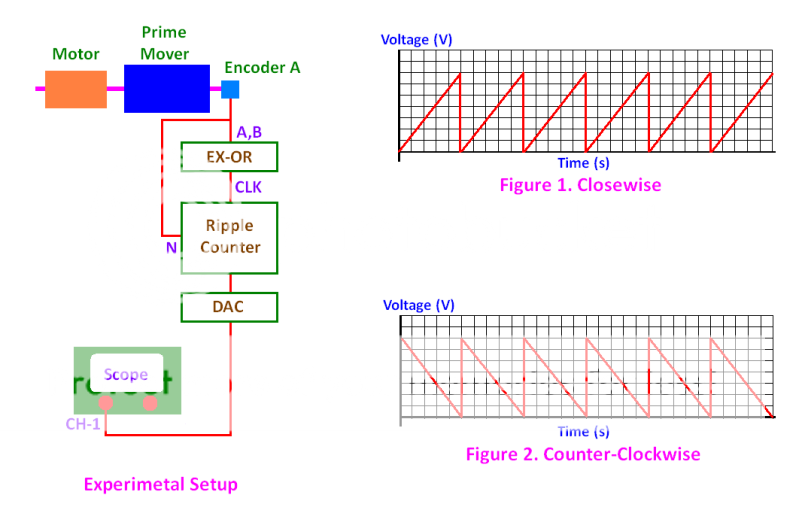
My experimental setup is as shown in attached image.
The prime mover is used to drive the motor at a constant speed, e.g. 1000rpm.
The encoder used in the system is Hengstler RI58-O/2000AS.41RB with 2000ppr.
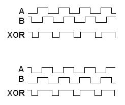
Output signals A and B of the encoder are input to an EX-OR gate.
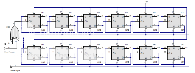
The CLK signal is then input to a 12-bit counter (uni-directional).
Index signal N from the encoder is used to reset the counter to zero every revolution made by the motor.
The output of the ripple counter is fetched to a DAC, which converts the 12-bit digital data to analog value.
A scope is used to capture the waveform output by the DAC.
When the system rotates in clockwise direction, the waveform captured by the scope is shown in Fig. 1.
When the system rotates in counter-clockwise direction, the waveform captured by the scope is shown in Fig. 2.
In my opinion, the captured waveform when the system rotates in clockwise direction should be same to that captured when it is rotates in counter-clockwise direction. What do you reckon?
Cheers.


