Ashin
Banned

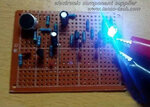
Q1 and Q2 form a two-stage audio amplifier circuit, the audio signal received by the MIC by the C1 coupled to the base of Q1, amplified by the collector directly to the base of Q2, Q2 in the collector to get a negative square wave, with To trigger a bistable circuit. R1 C1, the circuit frequency response for high sensitivity limit in the range of about 3kHz. When the power is switched on, the state of the bistable circuit is Q4 cut-off, Q3 is saturated, and LED1 is not bright. When the MIC receives the control signal, after two stages of amplification, the output of a negative square wave,after the differential treatment, the negative spike is applied to the base of Q3 through D1, and the circuit is quickly turned over and the LED 1 is turned on.


