Continue to Site

Welcome to EDAboard.com

Welcome to our site! EDAboard.com is an international Electronics Discussion Forum focused on EDA software, circuits, schematics, books, theory, papers, asic, pld, 8051, DSP, Network, RF, Analog Design, PCB, Service Manuals... and a whole lot more! To participate you need to register. Registration is free. Click here to register now.

DIY Bench Power Supply - Getting Started

Status
Not open for further replies.

meltmanbob

Newbie level 6
Newbie level 6
Joined
Apr 23, 2010
Messages
14
Helped
0
Reputation
0
Reaction score
0
Trophy points
1,281
Activity points
1,508
Basically I want to build a bench supply that is roughly 500 watts with multiple outputs that are both voltage and current variable and all of the appropriate protection devices. The thing I am stuck on right now is that for this power range, a SMPS seems most appropriate considering size and cost. So far I understand rectifying the mains AC, filtering it and using that as the DC source for PWM. Most of the SMPS designs I've seen have PFC which converts the rectified AC into high frequency and high voltage to a transformer. What I don't understand is why the rectified AC needs to be converted to high frequency and voltage.

It would seem to me that once you have the AC rectified and smoothed, use a PFC/PWM to chop it up, feed that through another rectifier and smoothing circuit which would branch off in parallel to multiple variable voltage regulators to feed the multiple outputs. Does anyone see anything wrong with this idea? Am I way off in left field or am I describing how SMPS actually work and something just isn't making that clear to me? Thanks for the help!
 

What I don't understand is why the rectified AC needs to be converted to high frequency and voltage.

It would seem to me that once you have the AC rectified and smoothed, use a PFC/PWM to chop it up, feed that through another rectifier and smoothing circuit which would branch off in parallel to multiple variable voltage regulators to feed the multiple outputs.
Electrical isolation (usually several kV at least), so that outputs are safe to touch and in no way directly connected to mains AC lines.

Transformers are still the most practical way to transfer that power from AC mains -> secondary side. And because the power transfer through a transformer becomes more efficient at higher frequencies, that's where the "chop up / PWM etc" on high-voltage primary side comes in. It's just a way to use smaller transformers, and reduce weight / size / cost of a power supply.

Note: PFC has nothing to do with this, that's just compensation circuitry to make a power supply more 'power company-friendly'. Especially important for high-power supplies like in PC's etc. Depending on design, it might of course be part of that high-voltage chopper circuit.

:!: In my opinion a SMPS that goes into a wall outlet is not a do-it-yourself job, especially not at power level you mention. Not unless you're a professional that did multiple output, high-power SMPS before. That is, apart from whether it's worth the trouble / cost to do this yourself.
 
Last edited:

So basically the transformer is used for isolation and the characteristics of the electricity are tailored to fit a smaller transformer? I understand that the higher the frequency, the smaller the transformer but I don't understand the need for high voltage. Does high voltage simply imply using the mains voltage? Or does it mean stepping the voltage up higher than the mains? I still don't see how the secondary side would be small if it's pulling 20-30 amps, is this also due to the switching? If this is the case then I'm assuming the wiring after the rectifier (after the transformer) would need to be sized for the current.

So at this point I'm wondering if I should just mod a store bought computer psu or continue with designing my own. What would be your suggestion? I'm guessing that at this point it would be easier to modify an existing one. Any idea's or direction on how to modify a store bought one to meets my goals? Thanks for the quick reply.
 

Does high voltage simply imply using the mains voltage?
Yes. But due to the nature of AC, X volts AC gets you >X DC voltage. And when you put that into a transformer coil, it's very possible voltages across that coil (temporarily) exceeds what you put into it. Not counting spikes / noise etc on the AC input. Hence the many hundreds of Volts-rated parts you find in these places.

So at this point I'm wondering if I should just mod a store bought computer psu or continue with designing my own.
How about buy psu that fits your needs? No need to void the warranty... :wink: Also what are your requirements, what kind of gear do you intend to power with your bench supply? (and what on earth would you need 500 W for?) :shock:
 

Ok, that makes sense about the higher than AC voltage, I just wasn't sure if it meant that it was stepped up or just the higher voltage from rectified AC.

Basically I want a relatively small (about the size of a computer psu) set up. I guess the easiest way to describe what I want is by the projects I would use it for. I want to run a bunch of UV LED's for making PCB's which is pretty low power. I also want to be able to use the supply on circuits I want to build such as a micro controller circuit. The higher powered projects would be a CNC spindle motor and the stepper motors. At some point I wanted to look into a DC-DC PSU so that I can run my computer directly from the deep cycle batteries in my van. Basically most of my projects will be low power regarding circuit projects but I wanted the extra power for testing out motors and such. Also money is a big concern so purchasing a pre-made supply is out.

I know that most people warn against messing with something like this but so far it doesn't seem extremely complicated. I have been an electrician apprentice and worked around some basic things that relate to my projects but at the very least I am familiar enough with electricity to be cautious and respect it. If I ask something that seems stupid or completely ignorant, well, that's why I'm asking instead of just going out and trying to test it. I fully understand that experimenting like this is not to be taken lightly especially with higher voltages and power.

Also I really would like the experience of building things out of electronics. I can built just about what ever I want mechanically but not electronically. I'm not interested in buying something, I'm a DIYer and part of this is that I want to learn which means screwing up some.
 

I want to run a bunch of UV LED's for making PCB's which is pretty low power.
Chances are you'll be annoyed when that's in use, powered by your bench psu & you want to do some experimentation at that time. For this kind of thing it's usually better to put together a dedicated power supply to go with that unit (or something that takes DC from whatever leftover wall plug adapter you have lying around).

I also want to be able to use the supply on circuits I want to build such as a micro controller circuit.
Such circuits need fixed +5V almost exclusively, and 1 or 2A is already a lot for this kind of stuff. Newer microcontrollers / digital logic might need 3.3V (usually even lower current), and sometimes a little higher voltage like 12V / -5V / -12V (couple a hundred mA is plenty) comes in handy for analog I/O tasks.

My advice: find a 50/60 Hz transformer in ~30-100W range, with output voltage such that rectified (+buffer capacitor) you wind up with around 20 to 30V DC (as that's suitable as input to most voltage regulators, lower & it will limit what you can get as output voltage, higher & it'll exceed what those regulators can take). If secondary winding has a center tap, that's a plus. If you can find a transformer with separate secondary windings, that's a bigger plus. Note that amps rating of a transformer applies when drawing AC, when rectified + buffer capacitor, you can usually divide amps rating by something like factor 1.5-2 (for example a 20V / 3A transformer may give you around 25V / 1.5-2A DC output).

Then have a look at what output voltages you think will be useful for low-power experiments (like microcontroller stuff), and use ordinary regulator(s?) like 7805, LM317 or LM25xx "Simple Switcher" series to make some DC outputs with that. You can add things like max current control, but that would make the circuit more complicated (I myself have rarely any use for a current limit on my bench supply, depending on your working style & experience it might be useful or not). Countless circuits / designs for this task floating around on the 'net.

If you start with a transformer that has multiple secondary windings, you can make independent outputs with it, that can be put in series if needed. Say you construct 2 (electrically isolated!) outputs that go from 0-15V, you have a single 0-30V to work with if needed.

Basically most of my projects will be low power regarding circuit projects but I wanted the extra power for testing out motors and such. Also money is a big concern so purchasing a pre-made supply is out.
For more 'oomph' :wink:, just grab an old PC power supply. ATX supplies have a signal on its connector to switch it on (it doesn't give output automatically when plugged in), and it might need a minimum load on some lines. Those would be easy mods.

They have many commonly used voltages (3.3 / 5 / 12 / -5 etc) with high current capability on several outputs. Perfect for powering small DC motors up to 100W or so. Cheap, 2nd hand possibly for free, there's no way you can build something yourself that even comes close in price / performance ratio. Note that higher-power might not be an advantage: more output current means more damage in case of mistakes... :oops:

You'll probably find that combination of such DIY bench supply + old PC supply is all you'll need for 99% of jobs. When you bump into remaining 1%, put together ad-hoc 'something' specifically for that task.

At some point I wanted to look into a DC-DC PSU so that I can run my computer directly from the deep cycle batteries in my van.
A 12V -> 110 / 230V AC inverter is probably the easiest 'fix' for that... cost depends on wattage & whether you're buying new or 2nd hand.
 
Last edited:

Why would I be annoyed with the UV LED's running off of the psu?

Micro-controllers - I realize that most of my projects will probably only require between 3.3-12v. Originally I was just going to modify a computer psu for all of this as it lends itself to very simple modification for these lower powered experiments. I'm assuming that in that situation, I could just add a simple variable voltage regulator that could get me between 1.5-9v and parallel an unregulated side off of the 12v out on the psu for a straight 12v line.

Transformer - Any advice on where to look and what frequency I should be feeding it with? I've checked Digikey and I know there are a few others such as Mouser. What about wrapping my own transformer? I'm sure that's asking for a can of worms but I've considered it simply because I haven't had much luck finding pre-made ones that are not overly expensive.

Basically the current output of a computer psu is not the problem but rather the voltage when it comes to anything with a motor. I have a few motor projects that will run off of 12v or less but I would like to have significantly higher voltage than 12v but with more amps that I could get if I used the 12+ and 12- sides of the psu. I'm perfectly content with have a psu that cannot fully drive high powered motors but the goal is to be able to supply it enough power to characterize it's behavior that could then be used to accurately estimate it's performance at higher power levels. I also realize that with lower voltage, I would need more current for the same power which is why I would like to have some higher voltages available. I plan on building the CNC spindle motor from scratch; higher voltage and less current means I can use smaller gauge wire. With regards to this I'm basically trying to leave a variety of power options available so I don't end up designing my motor around the psu.

Originally I was just going to make a small and simple supply for the LED's but I started to think about how many projects I have and how little I know. So in order to save some time I figured it would be a better investment of my time to create a general purpose supply that would allow me to either run completely or test and characterize the expected behavior of a circuit or system.

Note - most of these projects are centered around my van. I bought the van to live out of until I finish college in a couple of years since money is tight. I have 6 deep cycle batteries with 900ah; basically I can run 45 amps at 12v for 20 hours on these.
 

Why would I be annoyed with the UV LED's running off of the psu?
Because you can't use the psu then? (during the time it's powering those UV LEDs)

Note - most of these projects are centered around my van. I bought the van to live out of until I finish college in a couple of years since money is tight. I have 6 deep cycle batteries with 900ah; basically I can run 45 amps at 12v for 20 hours on these.
Develop electronic projects inside / around a van? 8-O Okay, if that's a suitable workspace for you... :-D

Anyway, I don't see a problem then: if you need ~12V unregulated, you could use the battery voltage directly. If you need that regulated, put a switching regulator in between that can drop or boost its output voltage as needed. For lower voltages, a simple linear regulator like 7805 or LM317 would do, or a step-down switching regulator if you want to use as little battery power as possible.

And if circuit you're working on needs to be isolated from the van's chassis, unhook a charged battery & use that as power source until it needs recharging. For all kinds of electronics projects a car battery should be very easy power source to start with. Low-voltage DC in, low-voltage DC out, doesn't get much easier than that. :razz: 12V-powered soldering iron should be easy to find as well.

I'm perfectly content with have a psu that cannot fully drive high powered motors but the goal is to be able to supply it enough power to characterize it's behavior that could then be used to accurately estimate it's performance at higher power levels. I also realize that with lower voltage, I would need more current for the same power which is why I would like to have some higher voltages available.
What you'd need is a step-up (switching) regulator, this is quite common thing but as soon as you move to higher-power range, your options might be limited as compared with "go to electronics shop & buy part". It's probably easiest to try and find a circuit that's used for similar purpose elsewhere (and then copy or buy that).
 

With multiple outputs why couldn't I use the psu while powering the LED's?

As far as the van goes, I'm not in it yet. I'm staying with family but that's so I can get the van to a decent standard. For the time being the power supply will be running off of 120VAC. I'm hoping that by starting with this power supply first, when it comes time to make/modify one for the computer, it should be a better product than the first.

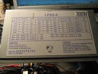
I think I have settled on a starting point and that is to buy a computer power supply that is around 300-500w and has an Energy Star rating of some level. As you said, it will offer me many of the standard voltages I would come across in my projects. The only thing it doesn't offer is variable control or voltages over 12v @ >2A.

The biggest question then boils down to how cost effective is it to turn the 12v rail in the psu into a variable output with a much higher max voltage and maintains at least 75% of the power originally available on that rail? For example, if the rail is rated for 20 amps and the max voltage for the variable output was 48v, then that variable output should be capable of 3.75A< output current < 5A. What about for the 5v rail? I'm asking about that one because I've seen a lot of the 5v rails have similar power ratings as the 12v rails.

The other stuff seems like it would be fairly easy to add in such as voltage, current, power, temperature meters. Also an adjustable current limiter and a switch selector to set what voltage is at the output terminals.

Down the road, I'm assuming it wouldn't be that difficult to modify the psu to bypass the AC stuff and provide an input for 12VDC from the car.
 

So at this point I am trying to find a way to convert the 12v and 5v rails from a computer psu to provide higher voltage yet maintain a decent amount of the rails rated power. If you have any ideas please let me know, so far the only IC's I've found might get me up to 36v @ 3A which is decent but I'm hoping for a bit more. Considering that the sole reason for higher power output is to test drive a cnc spindle, would it be possible to run 3 of the boost converters off of the same rail so that I could have one boost circuit per phase winding? At any rate, the biggest thing on my mind is how to increase the current and the voltage beyond what a standard boost IC can do, at least the ones from National. Thanks again.

Side note - Someone else responded and I got the email but it's not in the thread, any ideas why?
 

Side note - Someone else responded and I got the email but it's not in the thread, any ideas why?
Maybe it was a Personal Message?

Down the road, I'm assuming it wouldn't be that difficult to modify the psu to bypass the AC stuff and provide an input for 12VDC from the car.
For a PC power supply: forget that. Either put a car battery -> AC inverter in between (unnecessary complicated, and wasteful if the goal is to produce low voltage DC from a car battery), or reserve PC psu for situations where you can use mains AC.

so far the only IC's I've found might get me up to 36v @ 3A which is decent but I'm hoping for a bit more.
You're making the thinking error that IC itself should handle the voltage / current directly. For low-power applications that's the usual setup as it minimizes external component count.

But there's many power conversion IC's that can control external components (for example a high-voltage, high-current FET) to do the heavy lifting. That FET would see the high voltages & currents, but the control IC would only output an on/off signal, and use some kind of feedback (for example output voltage put through a resistor divider, or signal from an optocoupler) to see what's happening.

There's 1001 ways to do that, hence my suggestion of "look for circuit in similar application".


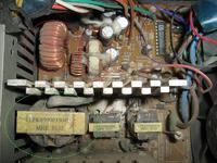
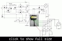
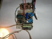
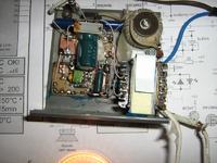
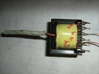
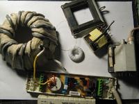
It is possible extract some different voltages from transformer taken from PS power supply, without additional transformations.

This transformer also possible to use up-down, secondary coils as primary.

However not all computer power supply unit are made on half-bridge scheme and accordingly not all their transformers are fit for such connections.
But it is easy to wind its on any approaching on size ferrite core, due to that half-bridge schematics do not require selecting the clearance in core and not so sensitive to correctness of winding.

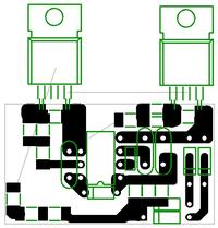
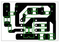
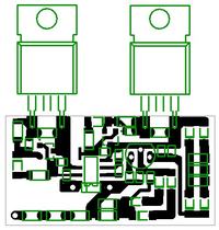
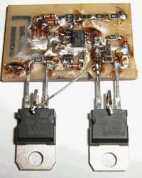
PCB possible slice by means of linen saw on metal for five minutes, without any of the chemistries ).

Unlike converters on sine wave, square wave converters without PWM not change voltage under load
in such big degree and possible not to use stabilization that simplifies filtering the unbent current.
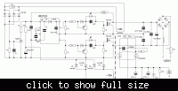
However in the case when is required regulation of the voltage, quite well using converters on cheap and broadly wide-spread MC34063 microcircuit.

 
Last edited:

The deleted post guy messaged me telling me why he deleted it, so that answers that.

I figured using a DC inverter in the van to run the bench supply would be very inefficient which is why I wanted to insert a DC input as a bypass for the AC input. I was assuming that from the psu outputs, back towards the AC input, up to a point would be pretty much the same as a DC to DC converter circuit. I would prefer to have one unit that could work from either input so I don't have to carry 2 different power supplies. When I think about it though, the psu components couldn't work from 12v.

One thing I think might work would be to use a 4 channel class D amp in the 400-500w range when it comes time to power the spindle motor. Assuming the 12v rail on the psu can provide the power for the amp then this should work if I can control the input signal to the amp. This will probably be very similar to controlling the spindle motor when the time comes.

Am I correct in thinking that an amp such as a car audio amp, are more or less high powered buck/boost voltage regulators? What I don't get is how they boost the voltage and the current beyond the IC's I've looked at. A transistor can output a voltage equal to or less than it's source voltage, dependent upon it's signal at the gate if I understand correctly. If this is the case, how do we convert the source voltage to a higher voltage using components that can handle the increased current that will come with it? I'll read up on that stuff some more.

If I were to build one from scratch, I think I would design everything off of a 12VDC source. Basically a DC input regulator feeding a multi-channel class D amp which should give me variable voltage well above the input voltage and be individually controllable on each channel. If I'm in the van, then I can just plug it in. If I'm using 120VAC, I would need to convert it to 12VDC. I think my focus should be on the amplifier design, the DC input regulator circuit I'm guessing shouldn't be too hard. As for being inside with 120VAC right now, I could just use a psu to power the amp. Instead of the $50+ psu's I was looking at, I could probably get away with a $35 one.

So to try and stick with finding something that is already what I need, I think that a class D amp with a 12v regulated input and a psu 12v rail circuit would work.
 

In PC PS at input 120V usually use schematics with doubler of the voltage.

apropos, there is opinion that schematics of PS with PWM does not be fit for HQ audio in view of high level of the hindrances.
how do we convert the source voltage to a higher voltage using components that can handle the increased current that will come with it? I'll read up on that stuff some more.
really, this all have a good description in books
 
Last edited:

Ok so I've done a bit more searching, seems as though Linear has a few IC's that could work but I have no clue where to start with their associated components. The one in particular I was looking at was the LTC3787. They have a lot that will operate between 4.5 and 40v input with an output up to 60-200v and up to about 10A. If these are appropriate for what I want then things might have just gotten a bit easier. Hypothetically I could use one of these chips per output and really not have to do much other than feed it the 12VDC from either the psu or directly from the van. What do you guys think? If I use a psu to provide the circuit 12v at home, it will already be isolated but I'm not sure about the batteries needing to be isolated.
 

Status
Not open for further replies.

Similar threads

Part and Inventory Search

Welcome to EDABoard.com

Sponsor

Back
Top