Vermes
Advanced Member level 4

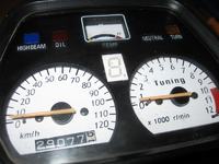
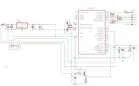
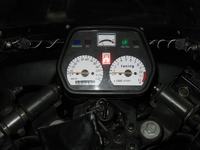
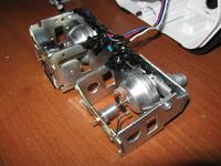
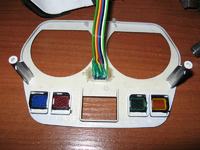
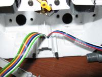
The principle of the display is based on the calculation of the ratio (r / speed) and allocating and displaying the appropriate indication. The first problem was “mining” the digital signal from mechanical clocks. This task is facilitated by their construction. There is a rotating magnet in all the clocks of this type. Additionally, sometimes its axis does not coincide with the axis of the hand. This enables pushing hallotron TLE4905 next to it. The signals from them were routed to INT0 and INT1, and their period was measured in interrupts. Then these two quantities were divided by each other and compared with the values stored in EEPROM.
In programming mode, ratios were stored in it, to be able to correctly calculate the indication.
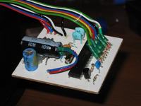
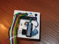
Additionally, “ultra bright display” was applied as an upgrade. In the day it proved itself, while at night it shone too bright what hurt eyes. Modification consisted of adding a board with few transistors, resistors and a phototransistor to adjust the brightness to the ambient brightness.

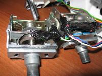
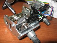
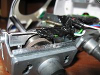
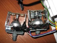
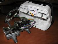
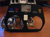
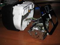
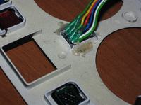
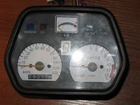
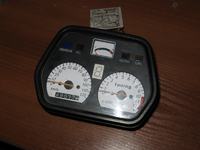
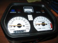
Link to original thread (useful attachment) – Wyświetllacz biegu do motocykla