Continue to Site

Welcome to EDAboard.com

Welcome to our site! EDAboard.com is an international Electronics Discussion Forum focused on EDA software, circuits, schematics, books, theory, papers, asic, pld, 8051, DSP, Network, RF, Analog Design, PCB, Service Manuals... and a whole lot more! To participate you need to register. Registration is free. Click here to register now.

Dimmer AC Circuit Resistor burns

Status
Not open for further replies.

ishtiaqshaheer

Junior Member level 3
Joined
Mar 17, 2017
Messages
26
Helped
0
Reputation
0
Reaction score
0
Trophy points
1
Location
India
Activity points
203
Hi,I'm doing a dimmer which is connected to a relay to work as a switch to Turn ON/OFF.
Now the circuit which I implemented is this

Dimmer.jpg

where I'm using MOC3021 & BT138-800E(TRIAC)

and according to the MOC3021 Datasheet its written as for a sensitive gate use this Fig.2
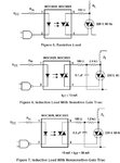
MOC3021.jpg

Now my real doubt is where to connect Load ? whether to MT2 or MT1?
because both the figures shows different connections
and I think there will be no much difference if we change the terminals
and when I start dimming then the resistor connected to MT2 is getting burnt whether its 1k,10k,10k1/2W anything
and for 2-3 times the dimming worked after that the resistor starts burning?
is it because any other device like MOC3021 got burnt within this 2-3times or any other reasons?

please help me through this
Thanks in Advance
 

if we change the terminals and when I start dimming then the resistor connected to MT2 is getting burnt whether its 1k,10k,10k1/2W anything
Are you using any strongly reactive load, such as a motor ?
If yes, it is missing a snubber on your circuit.
 

Are you using any strongly reactive load, such as a motor ?
If yes, it is missing a snubber on your circuit.

The load is Incandescent bulb, and I've a snubber circuit too.

IMG_20170519_174646.jpg


This is the circuit which I'm working on where relay is also a part of the circuit :)
 

Resistors > 2k will probably been overloaded and shouldn't been used. If 1k resistor burns, you have either a problem with non-triggering triac (defective or different type than BT138 with high trigger threshold) or a shorted capacitor. The capacitor must be rated for 250 VAC or at least 630 VDC.
 

Hi,

We don't see how you drive the MOC's LED.
According datasheet the max current to trigger the MOC is 15mA. I doubt there are 15mA.
But I don't know what happens when LED current is too low.

To be at the safe side: follow the datasheet recommendations.

Klaus
 

Resistors > 2k will probably been overloaded and shouldn't been used. If 1k resistor burns, you have either a problem with non-triggering triac (defective or different type than BT138 with high trigger threshold) or a shorted capacitor. The capacitor must be rated for 250 VAC or at least 630 VDC.

Thanks @FvM
can you please elaborate this ?

- - - Updated - - -

We don't see how you drive the MOC's LED.

Thanks @Klaus
MOCs LED is driven from the controller using program
int AC_LOAD = 3; // Output to Opto Triac pin
int dimming = 128; // Dimming level (0-128) 0 = ON, 128 = OFF
void setup()
{
Serial.begin(9600);
pinMode(AC_LOAD, OUTPUT); // Set the AC Load as output
attachInterrupt(digitalPinToInterrupt(2), zero_crosss_int, RISING); // Choose the zero cross interrupt
}
void zero_crosss_int() // function to be fired at the zero crossing to dim the light
{
// Firing angle calculation :: 50Hz-> 10ms (1/2 Cycle)
// (10000us - 10us) / 128 = 75 (Approx)
int dimtime = (75*dimming);
delayMicroseconds(dimtime); // Off cycle
digitalWrite(AC_LOAD, HIGH); // triac firing
delayMicroseconds(10); // triac On propogation delay
digitalWrite(AC_LOAD, LOW); // triac Off
}
void loop()
{
dimming = 90;
delay(7000);
dimming = 50;
delay(7000);
dimming = 20;
delay(7000);
}
 

Hi,

MOCs LED is driven from the controller using program
I am referring to currents (and/or voltages)

Klaus
 

Hi,

this is a useless value.

If you compare the 12.7mV with the values given in the datasheet you may see it can´t work.

I don´t like guessing, but with your given informations we need to.
So I assume you measured the voltage with a DVM .. and the control signal is PWM´d.
We can´t know if your DVM reading is the average value or the RMS value. We can´t know the drive voltage, we can´t know duty cycle. --> Impossible to verify your circuit.


Klaus
 

Sorry, even I'm unable to understand because now its showing as 0.53V but mostly its showing 0.0V (its always been varying)
but dimming is happening
so what may be the issue ?
 

Hi,

--> use a scope.
In cas eyou don´t have one, then buy one or lend one.


Klaus
 

any idea why it is not showing any voltage @ MOC?
and what are the cases where MOC & BT138 could be damaged?
hey @FvM, the cap 0.1uF should be 275VAC one?
 

Hi,now my dimming is working without any fault or damage of resistors when I replaced 0.1uF cap by 0.1uF/275VAC

But I'm still getting 0.4V @MOC3021 and 1.09V @4N35

And guys help me with the circuit I've attached where relay is also connected,the problem is when I send some instruction even without the relay being ON the dimming is happening instead it should only dim when relay is ON and according to the instruction given the dim should change
Thanks in advance
IMG_20170519_174646.jpg
 

Status
Not open for further replies.

Part and Inventory Search

Welcome to EDABoard.com

Sponsor

Back
Top