Vermes
Advanced Member level 4

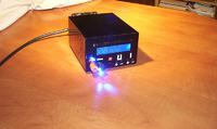
It is a digitally controlled power supply with variable voltage regulation 0-30V of 2A current efficiency.
The project was taken from: LINK.
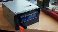
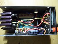
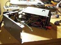
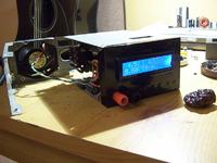
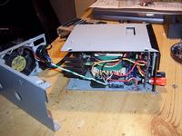
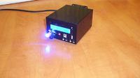
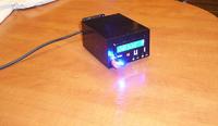
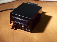
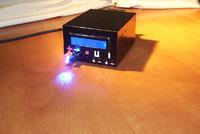
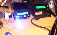
The assumption was to fit the board with the whole electronics, the display and the transformer in a small, handy housing from mini-ATX (Dell) power supply and proper placing the elements.
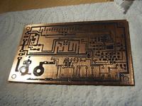
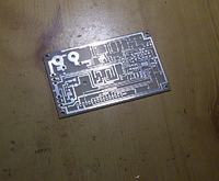
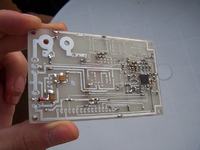
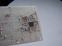
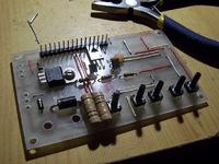
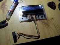
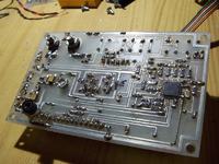
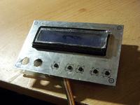
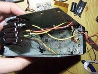
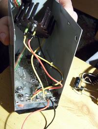
The board was designed to fit the front panel of the housing. Processor Atmega8 in version SMD, most of resistors SMD 1026 – all with tolerance of 1%. The elements were placed on one side PCB. Threaded elements are located between the display and the board. Resistor R36 should be soldered from the paths and connected by a wire to (-).
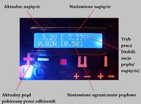
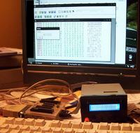
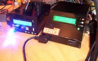
The power supply can work in two modes – as a current and voltage source (the current mode of operation is shown by the arrow). In addition to information about the set voltage and current limit, there is current actually consumed by the power supply and voltage actually appearing at the terminals on the display. The set values can be stored in the processor, so that you can start from them the next time the power supply is switched on.
The calibration and selecting the version of the power supply is done programmatically in hardware_settings.h file and compiling the program to the .hex file, in which the processor can be programmed.
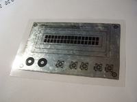
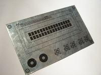
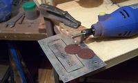
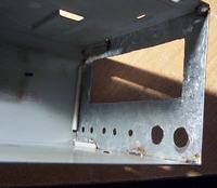
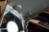
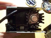
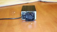
The front panel was made of galvanized steel and then soldered in place of the power grid. Fan gives adequate air circulation in the housing – cools the heat sink of the transistor (2N3055 was applied instead of BD245), the transformer and the rest of electronics. Holes, through which hot air comes out (in the case of higher load of the power supply), are drilled on both sides of the housing.
Photos:
Final effect:

Link to original thread (useful attachment) – Cyfrowo sterowany zasilacz 0-30V 2A by DaKKi