Continue to Site

Welcome to EDAboard.com

Welcome to our site! EDAboard.com is an international Electronics Discussion Forum focused on EDA software, circuits, schematics, books, theory, papers, asic, pld, 8051, DSP, Network, RF, Analog Design, PCB, Service Manuals... and a whole lot more! To participate you need to register. Registration is free. Click here to register now.

[SOLVED] Digital Tachometer issues

Status
Not open for further replies.

RMMK

Full Member level 3
Full Member level 3
Joined
Jun 12, 2013
Messages
163
Helped
1
Reputation
2
Reaction score
1
Trophy points
18
Location
Karachi
Activity points
1,461
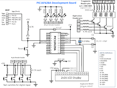
I followed this project : https://pic16f628a.blogspot.com/2010/10/contact-less-tachometer.html

But on powering the circuit I only read 0000 on 7-segment! NO OTHER VALUE! I cant find any rpm! I think I might have screwed with the IR DIODE AND PHOTODIODE STUFF since I didnt knew how to differentiate them! Is there a way so that i might check whether my IR DIODE is actually working??? Plz help me on troubleshooting this circuit!!! plzzzzzzzz
 

I followed the following steps to distinguish between the diodes and it seems like my set-up was correct! So where am I going wrong..... plzzzzz help!!!!!!


Colour of IR transmitter and receiver is different. However you may come across pairs which appear exactly same or even has opposite colours than shown in above pic and it is not possible to distinguish between TX and RX visually. In case you will have to take help of multimeter to distinguish between them.

Here is how you can distinguish between IR TX-RX using DMM :

Connect cathode of one LED to +ve terminal of DMM
Connect anode of the same LED to common terminal of DMM
(means connect LED such that It gets reverse biased by DMM )
Set DMM to measure resistance upto 2M Ohm.
Check the reading.
Repeat above procedure with second LED.
In above process, when you get the reading of the few hundred Kilo Ohms on DMM, then it indicated that LED that you are testing is IR sensor. In case of IR transmitter DMM will not show any reading.

- - - Updated - - -

Also I observed that whenever I give power to the circuit..... the 7 segment starts blinking up with some 2 sec intervals! and with time eventually it stops blinking and provides a constant light out (NO blinking)! For ease I am posting the program below!

//-------------- Function to Return mask for common cathode 7-seg. display
unsigned short mask(unsigned short num) {
switch (num) {
case 0 : return 0x3F;
case 1 : return 0x06;
case 2 : return 0x5B;
case 3 : return 0x4F;
case 4 : return 0x66;
case 5 : return 0x6D;
case 6 : return 0x7D;
case 7 : return 0x07;
case 8 : return 0x7F;
case 9 : return 0x6F;
} //case end
}
sbit IR_Tx at RB7_bit;
sbit DD0_Set at RA0_bit;
sbit DD1_Set at RA1_bit;
sbit DD2_Set at RA2_bit;
sbit DD3_Set at RA3_bit;
unsigned short i, DD0, DD1, DD2, DD3;
unsigned int Sample1, Sample2, Sample3, RPM;
void main() {

TRISB = 0b00000000; // Set PORTB direction to be output
TRISA = 0b00110000; // Set PORTA direction to be output
PORTB = 0x00; // Turn OFF LEDs on PORTB
CMCON = 7 ; // Disable comparators
RPM = 0; // Initial Value of Counter
OPTION_REG = 0b00111000; // TOCS=1 for Counter mode, PSA=1 for 1:1
IR_Tx = 0; // Turn OFF IR

do {

DD0 = RPM%10;
DD0 = mask(DD0);
DD1 = (RPM/10)%10;
DD1 = mask(DD1);
DD2 = (RPM/100)%10;
DD2 = mask(DD2);
DD3 = (RPM/1000);
DD3 = mask(DD3);

for (i = 0; i<=100; i++) {
PORTB = DD0;
DD0_Set = 1;
DD1_Set = 0;
DD2_Set = 0;
DD3_Set = 0;
delay_ms(5);
PORTB = DD1;
DD0_Set = 0;
DD1_Set = 1;
DD2_Set = 0;
DD3_Set = 0;
delay_ms(5);
PORTB = DD2;
DD0_Set = 0;
DD1_Set = 0;
DD2_Set = 1;
DD3_Set = 0;
delay_ms(5);
PORTB = DD3;
DD0_Set = 0;
DD1_Set = 0;
DD2_Set = 0;
DD3_Set = 1;
delay_ms(5);
}
DD3_Set = 0;

// First Sample
TMR0=0;
IR_Tx = 1;
Delay_ms(1000); // Delay 1 Sec
IR_Tx = 0;
Sample1 = TMR0*60;

// Second Sample
TMR0=0;
IR_Tx = 1;
Delay_ms(1000); // Delay 1 Sec
IR_Tx = 0;
Sample2 = TMR0*60;

// Third Sample
TMR0=0;
IR_Tx = 1;
Delay_ms(1000); // Delay 1 Sec
IR_Tx = 0;
Sample3 = TMR0*60;

RPM = Sample1 + Sample2 + Sample3;
RPM = RPM/3;

} while(1); // endless loop
}

- - - Updated - - -

IR_Circuit.jpg


Picture+2.png


the lcd part was negated in my circuit! I employed 7 segment with the h-part (of dots) also not included!
=>Seven segment displays used are common cathode type. The seven segments (a-g) are driven through RB0-RB6 respectively. The 4 common cathodes are controlled by RA0 (units digit) through RA3 (thousands digit).
=>IR Tx is connected to RB7
=>IR Rx Pulse is connected to RA4/T0CKI

- - - Updated - - -

Also i had a 4.433Mhz crystal which I used! I didnt input this exact value in program.... :(
 

Ok, lets check the basics.

During PIC programming:
1. If you are seeing all four digits light up it means the processor clock must be running but do you have the configuration fuse set to XT or HS?
2. Do you have the watchdog timer enabled? It should NOT be enabled for your program to work.
3. Do you have Low Voltage Programming (LVP) disabled? It should be disabled.

Hardware:
1. Do you have the 0.1uF capacitor wired across VSS and VDD pins AS CLOSE AS POSSIBLE TO THE PIC.
2. Are the crystal and the two crystal loading capacitors connected with short wires?

I'm not sure you need the extra diode in the IR receiver. You can test if the IR is working quite easily, connect a headphone/earphone in series with a 1K resistor across the 10K resistor in the collector of the BC557. Listen while you send some data from a TV/VCR remote control. If the receiver is working you should hear a buzz as the keys are pressed. If the buzz is there, your problem is in the IR transmitter stage.

Personally, I would increase the value of the 1.8K resistor to 47K or more, it's only there to prevent any leakage through the IR receiver biasing the transistor on when no light is present.

Brian.

1- it was HS and not XT!
2- yes watchdog timer is disabled
3- LVP is also disabled
4- 0.1uF capacitor is wired and its somewhat at a distance of 1-inches!

- - - Updated - - -

Another thing I did..... I actually threw some IR using my TV remote Control and interestingly the blinking of the 7 segment momentarily stopped whenever I press Remote control buttons! is it a sign that the circuit is receiving signals?? But no change in values occured! :(
 

Good, the electronics part seems to work. I think the software needs looking at though. You may have to live with the fact that multiplexing the display and measuring RPM are mutually exclusive. You may only be able to do one or the other, especially when you have delay routines to slow the display multiplexing, at best you will get some flickering as the multiplexing is disrupted. Can you show the full code so I can see what method for counting the pulses you are using please. Also give me some idea of how many pulses per second you are expecting and the maximum number it could ever reach.

I'm thinking a better solution would be to use two or even all three timers. One to open and close the period measuring window, one to count the pulses and maybe one to keep the multiplexing at a constant rate to reduce flickering. Incidentally, at the moment, your code only looks to be able to count 255 pulses per second, if you are using a toothed (cogs) wheel as the IR beam disrupter it means you could only measure slow speeds.

Brian.

here is the code!
//-------------- Function to Return mask for common cathode 7-seg. display
unsigned short mask(unsigned short num) {
switch (num) {
case 0 : return 0x3F;
case 1 : return 0x06;
case 2 : return 0x5B;
case 3 : return 0x4F;
case 4 : return 0x66;
case 5 : return 0x6D;
case 6 : return 0x7D;
case 7 : return 0x07;
case 8 : return 0x7F;
case 9 : return 0x6F;
} //case end
}
sbit IR_Tx at RB7_bit;
sbit DD0_Set at RA0_bit;
sbit DD1_Set at RA1_bit;
sbit DD2_Set at RA2_bit;
sbit DD3_Set at RA3_bit;
unsigned short i, DD0, DD1, DD2, DD3;
unsigned int Sample1, Sample2, Sample3, RPM;
void main() {

TRISB = 0b00000000; // Set PORTB direction to be output
TRISA = 0b00110000; // Set PORTA direction to be output
PORTB = 0x00; // Turn OFF LEDs on PORTB
CMCON = 7 ; // Disable comparators
RPM = 0; // Initial Value of Counter
OPTION_REG = 0b00111000; // TOCS=1 for Counter mode, PSA=1 for 1:1
IR_Tx = 0; // Turn OFF IR

do {

DD0 = RPM%10;
DD0 = mask(DD0);
DD1 = (RPM/10)%10;
DD1 = mask(DD1);
DD2 = (RPM/100)%10;
DD2 = mask(DD2);
DD3 = (RPM/1000);
DD3 = mask(DD3);

for (i = 0; i<=100; i++) {
PORTB = DD0;
DD0_Set = 1;
DD1_Set = 0;
DD2_Set = 0;
DD3_Set = 0;
delay_ms(5);
PORTB = DD1;
DD0_Set = 0;
DD1_Set = 1;
DD2_Set = 0;
DD3_Set = 0;
delay_ms(5);
PORTB = DD2;
DD0_Set = 0;
DD1_Set = 0;
DD2_Set = 1;
DD3_Set = 0;
delay_ms(5);
PORTB = DD3;
DD0_Set = 0;
DD1_Set = 0;
DD2_Set = 0;
DD3_Set = 1;
delay_ms(5);
}
DD3_Set = 0;

// First Sample
TMR0=0;
IR_Tx = 1;
Delay_ms(1000); // Delay 1 Sec
IR_Tx = 0;
Sample1 = TMR0*60;

// Second Sample
TMR0=0;
IR_Tx = 1;
Delay_ms(1000); // Delay 1 Sec
IR_Tx = 0;
Sample2 = TMR0*60;

// Third Sample
TMR0=0;
IR_Tx = 1;
Delay_ms(1000); // Delay 1 Sec
IR_Tx = 0;
Sample3 = TMR0*60;

RPM = Sample1 + Sample2 + Sample3;
RPM = RPM/3;

} while(1); // endless loop
}

- - - Updated - - -

A;so since I made this as an instrument for measuring angular velocity of a shaft for my dynamics project........ that shaft is driven by an electric motor...... I expect somewhat around 60 to 700 rpms!
 

I don't have the time to rewrite the code but I will offer some suggestions:

1. get rid of the switch() statement to look up the segment patterns. Replace it with a constant array like this-
"const unsigned char segments {0x3F, 0x06, 0x5B, 0x4F, 0x66, 0x6D, 0x7D, 0x07, 0x7F, 0x6F};"
the values never change so it's better to place them in ROM by using the 'const' declaration. You can now get the values by using 'segments[num];'

2. At the moment, you loop the display 100 times then stop for 3 seconds while the speed is checked. It would be better to use tmr0 interrupts to trigger the start of each display scan. Set it to interrupt say every 5mS, display a digit then move to the next digit in a loop. That will keep the display running continuously.

3. In the main() loop of the program, count the pulses by looking for rising or falling edges. When you see the edge you want, increment the pulse counter then wait for the pulse to finish before counting it again.

4. Use tmr1 as the timing gate (window) generator. Set it to interrupt at 100mS intervals (you can change the interval to calibrate or scale the results). At each interrupt, read the pulse count, transfer the reading to the display variables then reset it to zero. This will give a measure of pulses per 0.1 second.

If you do this you should be able to get a steady and flicker free 'live' display.

Brian.
 

Ahhh....... plz help me on it since my project submission date is just round the corner! its 6th of December!!!
 

I'll try, are you using the Mikroe C compiler that the original project used?
I use a different compiler but I do have a copy of the Mikroe C trial version. I'll investigate tomorrow (it's late at night here) and see if I can help. There is no way I can build any hardware at the moment though so you will have to do final debugging yourself.

Brian.

Thanks a lot! and yeah i am using MicroC!
 

Try this code. I wrote it in MikroeC and it compiles OK but for some reason I couldn't get the timers to work in simulation. It may just be that I'm not familiar with MikroeC and I did something wrong. Putting the hex code in a different simulator suggested it was working OK.
Code:
void NextLED();
void CalculateRPM();

//-------------- Array of segment values for common cathode 7-seg. display
const unsigned short segments[10] = {0x3F, 0x06, 0x5B, 0x4F, 0x66, 0x6D, 0x7D, 0x07, 0x7F, 0x6F};

sbit IR_Tx at RB7_bit;
sbit IR_Rx at RA4_bit;
unsigned short Digit[4], ActiveDigit = 0, LastRxState = 0;
unsigned int PulseCount;

void main()
{
 TRISB = 0b00000000; // Set PORTB direction to be output
 TRISA = 0b00110000; // Set PORTA direction to be output
 PORTB = 0x00; // Turn OFF LEDs on PORTB
 CMCON = 7; // Disable comparators
 OPTION_REG = 0b10000110; // TOCS=0 for internal clock Counter mode, PSA=0 for TMR0 prescaled 1:128
 T1CON = 0b00110001;  // Timer 1 counts internal clocks prescaled 1:8
 INTCON = 0b01100000; // Enable TMR0 and PIE interrupts
 PIE1 = 0b00000001; // Enable TMR1 interrupts
 INTCON |= (1<<GIE); // Enable global interrupts
 IR_Tx = 1; // Turn ON IR emitter

 // count rising edge transitions
 while(1)
 {
  if((IR_Rx == 1) && (LastRxState == 0)) PulseCount++;
  LastRxState = IR_Rx;
 }
}

// TMR0 times how long each Digit is displayed, TMR1 times how long pulses are counted for
 void interrupt()
 {
   if(INTCON.TMR0IF)
   {
    TMR0 = 0x53; // should be ~5mS at 4.433MHz clock
    NextLED();
    INTCON.TMR0IF = 0;
   }
  else if (PIR1.TMR1IF)
  {
    TMR1H = 0x27; TMR1L = 0x8C;  // should be ~100mS at 4.433MHz clock
    CalculateRPM();
    PulseCount = 0;
    PIR1.TMR1IF = 0;
  }
}

void CalculateRPM()
{
  Digit[0] = (short)PulseCount%10;
  Digit[1] = (short)(PulseCount/10);
  Digit[2] = (short)(PulseCount/100);
  Digit[3]= (short)(PulseCount/1000);
}

void NextLED()
{
 PORTA &= 0xF0; // turn all LED drives off
 if(ActiveDigit > 3) ActiveDigit = 0;
 PORTB = segments[Digit[ActiveDigit]];
 PORTA |= (1 << ActiveDigit);
 ActiveDigit++;
}

I used the same pins as your code so it should be electrically identical. I stress that I wrote it but have no way to build or debug it so you will have to tell me what happens (if anything!).

Brian.
 
  • Like
Reactions: RMMK

    RMMK

    Points: 2
    Helpful Answer Positive Rating
Sir I complied ur program and loaded it into 16F628A and the results are:-
1- Quite a lot/ fast blinking on the 7 segment!
2- No rpm detection yet!
3- When I threw some IR light using my TV Remote Control...... 7 segment did show some readings!
4- When I actually tried to see my IR LED on cell phone camera so that I might be able to see any IR light..... I didnt see it this time using this code! previously I was able to!
5- I used a disk which is more or less black and have pasted a white coloured paper! I even tried a fine piece of shiny aluminium sheet!
6- I think if somehow i get IR light this will work this time!!!!! We are a lot close! :)
 

Also interestingly whenever I pushes my board's reset button........ the IR LED glows for a moment and then goes off!!!

- - - Updated - - -

plz help! And tell me the name of the compiler u use in case.....
 

That's strange. The IR LED is turned on and left on. Your code turned it on and off as it measured pulses but mine should stay on all the time. Try simply connecting the IR LED across the supply through it's series resistor and check it stays lit up.

The fact that your remote control made the reading change is good, it shows that the counting routine is working. The remote will send pulses in brief bursts, it wont be continuous so don't expect a steady display.

Each digit on the display should light for about 4mS and they should light in sequence 1,2,3,4,1,2,3,4... At 4mS you shouldn't see much flickering but you can adjust the multiplexing speed by changing the value loaded into TMR0. A higher value will make the multiplex time shorter (faster scan). Check nothing else is wrong first though because it is already quite fast.

The compiler I normally use is 'WizC Pro' but I also use XC8/XC16 and often code in assembly language. WizC has a few 'quirks' but it has by far the best and fastest simulator I've ever used.

Brian.


Okay then I will try powering IR LED through the power source directly....... Will show u the results by afternoon! :p
 

Also betwixt plz wait i will show u results soon...... after i get back to home from university :)
 
Last edited by a moderator:

That's strange. The IR LED is turned on and left on. Your code turned it on and off as it measured pulses but mine should stay on all the time. Try simply connecting the IR LED across the supply through it's series resistor and check it stays lit up.

The fact that your remote control made the reading change is good, it shows that the counting routine is working. The remote will send pulses in brief bursts, it wont be continuous so don't expect a steady display.

Each digit on the display should light for about 4mS and they should light in sequence 1,2,3,4,1,2,3,4... At 4mS you shouldn't see much flickering but you can adjust the multiplexing speed by changing the value loaded into TMR0. A higher value will make the multiplex time shorter (faster scan). Check nothing else is wrong first though because it is already quite fast.

The compiler I normally use is 'WizC Pro' but I also use XC8/XC16 and often code in assembly language. WizC has a few 'quirks' but it has by far the best and fastest simulator I've ever used.

Brian.

As u said I connected the power supply to the IR LED through the same 68 ohms resistor and interestingly whenever I use the same battery pack which is connected to the uController....... the 7-segment goes out! BLANK! i.e., no display!
Then I connected two separate 9V batteries.... one for IR LED and the other for the uController+7 segment and now it gives some rpm values which seems quite weird! when i put it in front of my cpu fan some 6000, 7000, 8000 and 0000 readings are shown alternatively....... it seems as if only D1 of the 7 segment is showing display whereas the other 3 digits showing only 000! I checked for it whether they are connected right and it seems its okay! And yes the 7-segment display seems to be moving within milliseconds! Now what should i do??? Also i think i should tell u that I have placed both the transmitter as well as the receiver LED's parallel next to each other facing on the front.is this approach okay??
 

It's no wonder the IR made it go blank, you would be passing around 100mA through it! I suggest you change the 68 Ohm resistor to 390 Ohms (~20mA) before the LED burns out.

I have to add that it sounds like you are pushing the battery to the limit anyway, you really should be using a regulated mains power supply, if you are using one of those small batteries with two clips at one end, it will struggle to provide sufficient voltage, the way it fails under only 100mA extra load confirms this.

Unfortunately, the simulation in Mikroe C doesn't show the timers counting so no interrupts are triggered. I'm not sure why but it prevents me seeing the multiplexing so I can't check if the correct digits are being shown.
Please try changing these lines:
Code:
void CalculateRPM()
{
  Digit[0] = 4;
  Digit[1] = 3;
  Digit[2] = 2;
  Digit[3] = 1;
}
and run it to see if it displays '1234'. What I'm trying to establish is whether the displaying routine is at fault or there is a calculation problem. Putting known values in the program should narrow it down.

If it does display '1234' the problem is almost certainly due to the calculation mixing 8-bit and 16-bit values, that's why I added the (short) cast to the variables but it may not be working as expected.

Brian.

Yup it is displaying 4321........ on doing as above!
 

The display routine seems to be working fine.
I'm tied up with another job right now and there is no chance I can help before your deadline. The bug is in the calculateRPM() routine, the formula for working out the speed is not working properly. I'll have to let you work that one out for yourself but I think you can see how it processes the result, the thousands digit goes in Digit[0], hundreds in Digit[1], tens in Digit[2] and units in Digit[0]. Let me know how you get on.

Please remember it shows the pulses per 0.1 seconds interval at the moment, you can adjust the timing interval with the value loaded into TMR1 but if you need longer intervals, use a software variable to count several shorter intervals, do not use any delay routines as these will disrupt the display multiplexing.

Brian.
 

Status
Not open for further replies.

Part and Inventory Search

Welcome to EDABoard.com

Sponsor

Back
Top