Continue to Site

Welcome to EDAboard.com

Welcome to our site! EDAboard.com is an international Electronics Discussion Forum focused on EDA software, circuits, schematics, books, theory, papers, asic, pld, 8051, DSP, Network, RF, Analog Design, PCB, Service Manuals... and a whole lot more! To participate you need to register. Registration is free. Click here to register now.

Digital Input Range Select

Status
Not open for further replies.

ric_vas

Member level 4
Member level 4
Joined
Jun 30, 2005
Messages
71
Helped
3
Reputation
6
Reaction score
0
Trophy points
1,286
Activity points
1,663
Hi,

not sure if this is the right forum, anyway..

I need to design a circuit to support three levels of "digital" input to a microcontroller (PIC) working out of a 5Vdc power supply.

The input levels: 0-125Vdc, 0-48Vdc, 0-24Vdc.

I can use jumpers to select from them.

What you recommend in terms of protection circuit? Are series resistance, opto-couplers, maybe zener, enough?

Thanks in advance.

Ric
 

You can make voltage divider to 4v - 5v for each input and to drive it with FET transistors like 2n7000 with pull-up resistor connected to the board logic supply
Its only 6 resistors no jumpers needed
Take care for the 125v input resistors maximum voltage rating and power
 

Hi Jepeto,

Thanks for helping.

I didn't understand the "no jumper needed" part. Maybe I was not so clear, there will be only one physical input conector which can receive a 125, 48 or 24 Vdc (not at the same time obvioulsy).

I'm also considering to use an opto before the microcontroller. Will I still need the FET you suggested?

Best regards,

Ric
 

If you use a Zenner diode to avoid over-voltage, take care with resistor value, due the behaviour of this type of diode is non-linear under nominal secified courrent.
 

Zenner diode or standard diodes and opto coupler will be good
Just need to calculate the right resistors value for 125v and 24v inputs
No FET needed
 

Thanks guys for the inputs!!

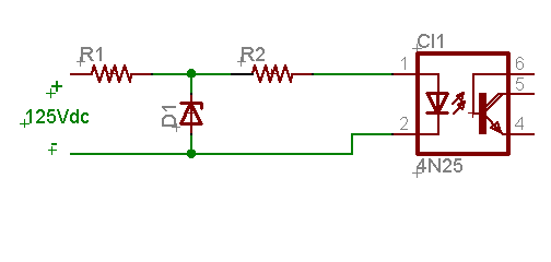
Let's see if I got it:

58_1163555623.gif


Is that correct? Then I will select R1 and R2 so that the Zener and Opto receive the expected current to operate.

Ric
 

That project is standing by :( I didn't have a chance to test it but I think that's the way to go about it.

I would make use of jumpers to select between different voltage divider nets for each input range needed.

Regards,

Ric
 

Status
Not open for further replies.

Part and Inventory Search

Welcome to EDABoard.com

Sponsor

Back
Top