Continue to Site

Welcome to EDAboard.com

Welcome to our site! EDAboard.com is an international Electronics Discussion Forum focused on EDA software, circuits, schematics, books, theory, papers, asic, pld, 8051, DSP, Network, RF, Analog Design, PCB, Service Manuals... and a whole lot more! To participate you need to register. Registration is free. Click here to register now.

[SOLVED] difficult to get 27MHz reception

Status
Not open for further replies.

obrien136

Junior Member level 2
Joined
May 27, 2014
Messages
24
Helped
0
Reputation
0
Reaction score
0
Trophy points
1
Activity points
174
Hello,
I have been trying to develop a control system for an RC vehicle. using a different kind of approach. I haave been informed thst it is not very practical one, but I'm trying it anyway just to satidfy my curiosity. The schematics of the tranmitter and receiveer as well as amps developed for outputs are attached.

View attachment img-Y06063827.pdf
View attachment img-Y06063940.pdf
View attachment img-Y06064015.pdf
View attachment img-Y06064050.pdf
View attachment img-Y06064138.pdf
View attachment img-Y06064200.pdf

Can anyone explain why I get very little (a few mV RMS)
or no output from the receiver? THe transmitter appears to be transmitting and it gets a modulation signal. The receiver oscillator is working but currently I am gettting no output from the receiver.
 
Last edited by a moderator:

Frank,

I can't find the website again where I got the scematic. It is supposed to work I suppose as a zero IF receiver, or direct conversion, I'm not sure, THe crystals are same. I have tried many receiver circuits. Can you recommend a good one?

George
 

you should give us your crystal's information and the principal component used (transistor or what) ??
 

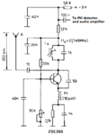
Like in one of the posted articles, you wrongly copied the schematic of the super-regenerative AM receiver. Since it is so simple its performance is horrible but is used in cheap walkie-talkies and cheap toy cars for kids.

Here is a manufactured super-regen receiver circuit used in a cheap toy car:
 

Attachments

  • toy car super-regen radio.png
    toy car super-regen radio.png
    9.9 KB · Views: 127

Do you want make a simple AM receiver or you want make a good one with high performance ?

Maybe this one will satisfy your needs
**broken link removed**
 

you should give us your crystal's information and the principal component used (transistor or what) ??

I got the xtal about a year ago and I can' t read the info on it. I am using a 2n4402 as the element
 

There are many types of RC controllers, the most common are pulse position modulated FM. Is this what you would like to try?

I think you were trying AM which gives inferior quality due to amplitude modulation of the antenna positions and the AGC response time must be faster than the bandwidth of the signal modulation due to fading losses with a rapid shifting mobile transmitter. The Q factor also affects the gain of each stage but you need high gain with AGC to normalize the output. With motion, dead spots giving deep attenuation, you need very high gain and very fast AGC.

In any case here is one Futaba AM transmitter using a 27MHz Crystal on the right corner.
**broken link removed**
In any radio system, the quality of the signal depends on the Q of multi-stage filters and noise threshold.

Here is an old Futaba FM Modulator for PPM.
**broken link removed**


For more ideas **broken link removed**

It is better to understand why a good design works well than to try to understand why something that is insufficient works poorly.

Here is a good AM AGC superhet receiver with cascaded filter channels to block adjacent channels.
1st stage Crystal Osc mixes antenna filtered signal thru many stages of IF filtering. Ceramic resonators were not available back then for the IF which make it much easier now.
image057.jpg
 

THanks folks I know what direction to go in now/
 

Status
Not open for further replies.

Part and Inventory Search

Welcome to EDABoard.com

Sponsor

Back
Top