Continue to Site

Welcome to EDAboard.com

Welcome to our site! EDAboard.com is an international Electronics Discussion Forum focused on EDA software, circuits, schematics, books, theory, papers, asic, pld, 8051, DSP, Network, RF, Analog Design, PCB, Service Manuals... and a whole lot more! To participate you need to register. Registration is free. Click here to register now.

Difficult in reading the DIP switches and generating the PULSE WIDTH usingPIC16f627A

Status
Not open for further replies.

skubaig

Newbie level 6
Newbie level 6
Joined
May 19, 2010
Messages
13
Helped
0
Reputation
0
Reaction score
0
Trophy points
1,281
Activity points
1,361
Code:
;***************PortB Variable definitions

SWPORTB 	EQU		B'00101111'		; Switches are connected to PORTB
;SWTRIS		EQU		TRISB
SW1			EQU 	0
SW2 		EQU		1
SW3			EQU		2
SW4			EQU		3
PICOUT		EQU		4
PICTXIn		EQU		5
;End of Definitions
		UDATA
Delay_i		res 1	; Delay Loop Count
;***************************************************
;********BAUDRATE SETTINGS**************************

#define 	BD0		0x00	;BD0=921600 time delay =0.01041ms
#define 	BD1		0x01	;BD1=460800 time delay =0.02082ms
#define		BD2		0x02	;BD2=230400 time delay =0.04166ms
#define		BD3		0x03	;BD3=115200 time delay = 0.0833ms
#define		BD4		0x04	;BD4=57600 time delay =0.1666ms
#define		BD5		0x05	;BD5=38400 time delay =0.25ms
#define		BD6		0x06	;BD6=19200 time delay = 0.5ms
#define		BD7		0x07	;BD7=9600 time delay = 1ms
#define		BD8		0x08	;BD8=4800 time delay = 2ms 
#define		BD9		0x09	;BD9=2400 time delay = 4ms
#define		BD10	0x0a	;BD10=1200 time delay = 8ms
#define		BD11	0x0b	;BD11= 300 time delay = 32ms
#define		BD12	0x0c	;BD12 = 110 time delay = 87ms
;****************************************************	
;LOOKUP TABLE***************************************

;***************** Main Program


		org 0x0000
		

		;Options 
		bsf 	STATUS,RP0			;Select Bank1

		movlw	B'00000000'			
							;bit7-Set to disable weak pull-ups PORTB
							;bit6-falling edge interupt
							;bit5-TMR0 clock source internal cycle clock
							;bit4-NA
							;bit3-Prescaler assigned to TMR0
							;bit<2:0> TMR0 prescaler 1:128
		movwf	OPTION_REG
		;interrupts
		movlw 	B'00000000' ; 0 -bit7-Global interupts disabled - enable later
							; 0 -bit6-Peripheral interupts disabled - enable later
							; 0 -bit5-TMR0 overflow disabled
							; 0 -bit4-INTE disabled external interupts RB0
							; 0 -bit3-RB port change interupt disabled
							; 0 -bit2-TMR0 overflow flag bit cleared
							; 0 -bit1-INTF external interupt flag 
							; 0 -bit0-RB port change flag bit cleared
		movwf	INTCON


		movlw 	b'00101111'			;Set PortB 0,1,2,3,5 as input and pin4 as output
		movwf   TRISB
		bcf		STATUS,RP0			;Select Bank0


;	
MainLoop
		bsf	STATUS, RP0
		movlw 	b'00101111'			;Set PortB 0,1,2,3,5 as input and pin4 as output
		movwf   TRISB
		bcf	STATUS,RP0			;Select Bank0
		movf 	SWPORTB, W			; read PORTB
		swapf	SWPORTB, W
		andlw 	0x0F 				; Consider only the lower 4-bits RB0-RB3
		addwf	PCL,1
		goto 	BAUDRATE_0
		goto 	BAUDRATE_1
		goto	BAUDRATE_2
		goto	BAUDRATE_3
				
		goto MainLoop
		

BAUDRATE_0
	
;Here0	
H1		btfss	PORTB, PICTXIn		; Test for Tx pin Low
		goto 	H1					; Goto H1 loop
		bsf		PORTB, PICOUT		; Set pin4 of portb high
		call	Delay0.01041ms			; call 1ms delay	

H2		btfsc	PORTB, PICTXIn		; Test for Tx pin High
		goto	H2
		bcf		PORTB, PICOUT		; Set pin4 of portb low
		call 	Delay0.01041ms
	;	goto Here0
BAUDRATE_1
	
;Here1
H3		btfss	PORTB, PICTXIn		; Test for Tx pin Low
		goto 	H3					; Goto H1 loop
		bsf		PORTB, PICOUT		; Set pin4 of portb high
		call	Delay0.02082ms			; call 1ms delay	
H4		btfsc	PORTB, PICTXIn		; Test for Tx pin High
		goto	H4
		bcf		PORTB, PICOUT		; Set pin4 of portb low
		call 	Delay0.02082ms
;		goto Here1

;	
BAUDRATE_2


;Here2	
H5		btfss	PORTB, PICTXIn		; Test for Tx pin Low
		goto 	H5					; Goto H1 loop
		bsf		PORTB, PICOUT		; Set pin4 of portb high
		call	Delay0.04166ms			; call 1ms delay	
H6		btfsc	PORTB, PICTXIn		; Test for Tx pin High
		goto	H6
		bcf		PORTB, PICOUT		; Set pin4 of portb low
		call 	Delay0.04166ms
;		goto Here2

BAUDRATE_3
	
;Here3	
H7		btfss	PORTB, PICTXIn		; Test for Tx pin Low
		goto 	H7					; Goto H1 loop
		bsf		PORTB, PICOUT		; Set pin4 of portb high
		call	Delay0.08333ms			; call 1ms delay	
H8		btfsc	PORTB, PICTXIn		; Test for Tx pin High
		goto	H8
		bcf		PORTB, PICOUT		; Set pin4 of portb low
		call 	Delay0.08333ms
;		goto 	Here3

In the above code 4 DIP switches are connected to the 4pin of portB from 0-3 pins......depending on 4-bits and pin 5 of PORTB is connected to TX line of usb to 232 converter (FDTI MM232R) the pic monitors the 4DIP switches and the pin 5 depending on these conditions a output pin 4 of PORTB should generate a pulse.........pls any suggestion on the above code is appreciated .........
 
Last edited by a moderator:

Hi,

You will find this simpler way works fine.


Code:
MainLoop

    bsf 	STATUS, RP0
    movlw	b'00101111' ;Set PortB 0,1,2,3,5 as input and pin4 as output
    movwf 	TRISB
    bcf 	STATUS,RP0 ;Select Bank0

    movf PORTB, W		; read PORTB
    andlw 0x0F 			; Mask upper nibble / Consider only the lower 4-bits RB0-RB3
	movwf	VALUE		; save result in VALUE

	movlw	0x01		; is VALUE = 01
	subwf	VALUE,W
	btfsc	STATUS,Z
	goto	H1		; Yes, goto H1

	movwf	VALUE		; is value = 02
	movlw	0x02
	subwf	VALUE,W
	btfsc	STATUS,Z
	goto	H2		; goto H2 

				; etc


    goto MainLoop
 

Hi wp100,

Thank you very much for your reply.......I have modified the code ........but it not working.........the changes are as follows

Code:
MainLoop
		bsf		STATUS, RP0
		movlw 	b'00101111'			;Set PortB 0,1,2,3,5 as input and pin4 as output
		movwf   TRISB
		bcf		STATUS, RP0
		movf 	PORTB, W			; read PORTB
		andlw 	0x0F 				; Consider only the lower 4-bits RB0-RB3
		movwf	VALUE				; Save result in VALUE

	;	movlw	BD0					; is VALUE = 0x00
		subwf	VALUE, 0x00			
		btfsc	STATUS, Z
		goto 	BD_0

		movwf	VALUE			; is value=0x01
	;	movlw	BD1				;BD1=0x01
		subwf	VALUE, 0x01		; 
		btfsc	STATUS, Z
		goto 	BD_1

		movwf	VALUE			; is value=0x02
	;	movlw	BD2				;BD2=0x02
		subwf	VALUE, 0x02		; 
		btfsc	STATUS, Z
		goto	BD_2

		movwf	VALUE			; is value=0x03
	;	movlw	BD3				;BD3=0x03
		subwf	VALUE, 0x03		; 
		btfsc	STATUS, Z
		goto	BD_3

		movwf	VALUE			; is value=0x04
	;	movlw	BD4				;BD4=0x04
		subwf	VALUE, 0x04		; 
		btfsc	STATUS, Z
		goto	BD_4

		movwf	VALUE			; is value=0x05
	;	movlw	BD5				;BD5=0x05
		subwf	VALUE, 0x05		; 
		btfsc	STATUS, Z
		goto	BD_5

		movwf	VALUE			; is value=0x06
	;	movlw	BD6				;BD6=0x06
		subwf	VALUE, 0x06		; 
		btfsc	STATUS, Z
		goto 	BD_6


		movwf	VALUE			; is value=0x07
	;	movlw	BD7				;BD1=0x07
		subwf	VALUE, 0x07		; 
		btfsc	STATUS, Z
		goto 	BD_7

		movwf	VALUE			; is value=0x08
	;	movlw	BD8				;BD1=0x08
		subwf	VALUE, 0x08		; 
		btfsc	STATUS, Z
		goto	BD_8

		movwf	VALUE			; is value=0x09
	;	movlw	BD9				;BD1=0x09
		subwf	VALUE, 0x09		; 
		btfsc	STATUS, Z
		goto	BD_9

		movwf	VALUE			; is value=0x0a
	;	movlw	BD10				;BD1=0x0a
		subwf	VALUE, 0x0A		; 
		btfsc	STATUS, Z
		goto	BD_10

		movwf	VALUE			; is value=0x0b
	;	movlw	BD11				;BD1=0x0b
		subwf	VALUE, 0x0B		; 
		btfsc	STATUS, Z
		goto	BD_11
	
		movwf	VALUE			; is value=0x0c
	;	movlw	BD12				;BD1=0x0c
		subwf	VALUE, 0x0C		; 
		btfsc	STATUS, Z
		goto	BD_12
		

		movwf	VALUE		; is value = 0x0d
	;	movlw	BD13		; BD13=0x0d
		subwf	VALUE, 0x0D
		btfsc	STATUS, Z
		goto	BD_13
	
	goto MainLoop
		

BD_0
	
Here0

H1		btfsc	PORTB, PICTXIn		; Test for Tx pin Low
		goto 	H1					; Goto H1 loop
		bsf		PORTB, PICOUT		; Set pin4 of portb high
		call	Delay0.01041ms			; call 1ms delay	
	;	call	Delay1ms 		; call 1ms delay
H2		btfss	PORTB, PICTXIn		; Test for Tx pin High
		goto	H2
		bcf		PORTB, PICOUT		; Set pin4 of portb low
		call 	Delay0.01041ms
	;	call	Delay1ms 		; call 1ms delay
		goto Here0
BD_1
	
Here1
	
H3		btfsc	PORTB, PICTXIn		; Test for Tx pin Low
		goto 	H3					; Goto H1 loop
		bsf		PORTB, PICOUT		; Set pin4 of portb high
		call	Delay0.02082ms			; call 1ms delay	
	;	call	Delay1ms 		; call 1ms delay
H4		btfss	PORTB, PICTXIn		; Test for Tx pin High
		goto	H4
		bcf		PORTB, PICOUT		; Set pin4 of portb low
		call 	Delay0.02082ms
;		call	Delay1ms 		; call 1ms delay

		goto Here1

	
BD_2


Here2
		
H5		btfsc	PORTB, PICTXIn		; Test for Tx pin Low
		goto 	H5					; Goto H1 loop
		bsf		PORTB, PICOUT		; Set pin4 of portb high
		call	Delay0.04166ms			; call 1ms delay
		;call	Delay1ms 		; call 1ms delay	
H6		btfss	PORTB, PICTXIn		; Test for Tx pin High
		goto	H6
		bcf		PORTB, PICOUT		; Set pin4 of portb low
		call 	Delay0.04166ms
	;	call	Delay1ms 		; call 1ms delay

		goto Here2

BD_3


Here3	
	
H7		btfsc	PORTB, PICTXIn		; Test for Tx pin Low
		goto 	H7					; Goto H1 loop
		bsf		PORTB, PICOUT		; Set pin4 of portb high
		call	Delay0.08333ms			; call 1ms delay
	;	call	Delay1ms 		; call 1ms delay	
H8		btfss	PORTB, PICTXIn		; Test for Tx pin High
		goto	H8
		bcf		PORTB, PICOUT		; Set pin4 of portb low
		call 	Delay0.08333ms
	;	call	Delay1ms 		; call 1ms delay
		goto 	Here3


BD_4
	
Here4

H9		btfsc	PORTB, PICTXIn		; Test for Tx pin Low
		goto 	H9					; Goto H1 loop
		bsf		PORTB, PICOUT		; Set pin4 of portb high
		call	Delay0.1666ms			; call 1ms delay
	;	call	Delay1ms 		; call 1ms delay	
H10		btfss	PORTB, PICTXIn		; Test for Tx pin High
		goto	H10
		bcf		PORTB, PICOUT		; Set pin4 of portb low
		call 	Delay0.1666ms
	;	call	Delay1ms 		; call 1ms delay

		goto	Here4


Please any suggestions........thanks
 
Last edited by a moderator:

Hi,

Ah, afraid I included the line ' movwf VALUE ' in each routine - it should not be there.

Also you cannot add the value onto the SUBWF instruction.


You code needs to be -

movf PORTB, W ; read PORTB
andlw 0x0F ; Consider only the lower 4-bits RB0-RB3
movwf VALUE ; Save result in VALUE


then - Each routine should be like

movlw BD1 ;BD1=0x01
subwf VALUE,W ; VALUE is not changed by the Sub instruction
btfsc STATUS, Z
goto BD_1


Are you using SIM or Debugger to run your code, are you Single Stepping though the code to see what is happening ?

Hi Wp100,

I am using PICkit2 onboard Debugger but it is showing me the error " PK2Error0028: Ubale to enter debug mode"
any suggestions please.......
 

I am using PICkit2 onboard Debugger but it is showing me the error " PK2Error0028: Ubale to enter debug mode"

Hi,

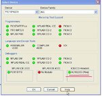
If you look at MPlab, Configure, Select Device you will see that the box at the bottom right states a Header is required to run PK2 debugger with the 627A.

Basically a header is a debugger compatible pic chip that connects between the Pk2 and the 627a.

You can mess around buying one and the interconnects - but would strongly suggest you buy a Debugger compatible chip instead, so much simpler and the chip will likely have many more features anyway.

Look at the 16F88 as a pin complatible replacement for the 627A.

In the mean time you can still check a lot of functions out using MPLABs SIM, just load VALUE with a number instead of reading PORTB or you can use ISIS for a full time simulation - think you have got that according to your profile ?
 

Attachments

  • ScreenShot001.jpg
    ScreenShot001.jpg
    45 KB · Views: 99

Thank you very much for your help.I have tried using the simulator MPLABSIM assigned 0x07 to the VALUE but it is not jumping to the BD_7 instead it is cheaking sequencially from BD_0 any suggestions pls

CBLOCK 0x07
VALUE
ENDC
;***************** Main Program


org 0x00


;Options
bsf STATUS,RP0 ;Select Bank1

movlw B'00000000'
;bit7-Set to disable weak pull-ups PORTB
;bit6-falling edge interupt
;bit5-TMR0 clock source internal cycle clock
;bit4-NA
;bit3-Prescaler assigned to TMR0
;bit<2:0> TMR0 prescaler 1:128
movwf OPTION_REG
;interrupts
movlw B'00000000' ; 0 -bit7-Global interupts disabled - enable later
; 0 -bit6-Peripheral interupts disabled - enable later
; 0 -bit5-TMR0 overflow disabled
; 0 -bit4-INTE disabled external interupts RB0
; 0 -bit3-RB port change interupt disabled
; 0 -bit2-TMR0 overflow flag bit cleared
; 0 -bit1-INTF external interupt flag
; 0 -bit0-RB port change flag bit cleared
movwf INTCON


bsf PCON, OSCF ;Select 4MHz Clock
movlw b'00101111' ;Set PortB 0,1,2,3,5 as input and pin4 as output
movwf TRISB
bcf STATUS,RP0 ;Select Bank0


;
MainLoop
bsf STATUS, RP0
movlw b'00101111' ;Set PortB 0,1,2,3,5 as input and pin4 as output
movwf TRISB
bcf STATUS, RP0
movf PORTB, W ; read PORTB
andlw 0x0F ; Consider only the lower 4-bits RB0-RB3
movwf VALUE ; Save result in VALUE=0x07

movlw BD0 ; is VALUE = 0x00
subwf VALUE, W
btfsc STATUS, Z
goto BD_0


movlw BD1 ;BD1=0x01
subwf VALUE, W ;
btfsc STATUS, Z
goto BD_1


movlw BD2 ;BD2=0x02
subwf VALUE, W ;
btfsc STATUS, Z
goto BD_2


movlw BD3 ;BD3=0x03
subwf VALUE, W ;
btfsc STATUS, Z
goto BD_3


movlw BD4 ;BD4=0x04
subwf VALUE, W ;
btfsc STATUS, Z
goto BD_4


movlw BD5 ;BD5=0x05
subwf VALUE, W ;
btfsc STATUS, Z
goto BD_5


movlw BD6 ;BD6=0x06
subwf VALUE, W ;
btfsc STATUS, Z
goto BD_6


movlw BD7 ;BD7=0x07
subwf VALUE, W ;
btfsc STATUS, Z
goto BD_7


movlw BD8 ;BD8=0x08
subwf VALUE, W ;
btfsc STATUS, Z
goto BD_8
 

Hi,

Change Cblock back to 0x20, thats the address of where VALUE resides, not any value it may contain.

In your code use this

; movf PORTB, W ; read PORTB
; andlw 0x0F ; Consider only the lower 4-bits RB0-RB3

movlw 0x07 ; load W with h 07
movwf VALUE ; Save result in VALUE=0x07
 
Thanks you very much it works........
 

Hi,

Well done !


You can also use SIM to time your Delay routines.

You use a BREAKPOINT just before and / or after the Delay routine ( if you have more than one breakpoint available)

Then start the STOPWATCH feature and RUN the code between the Breakpoints to get the time.

You can use this link to get your Delay parameters.**broken link removed**
 

Status
Not open for further replies.

Part and Inventory Search

Welcome to EDABoard.com

Sponsor

Back
Top