Continue to Site

Welcome to EDAboard.com

Welcome to our site! EDAboard.com is an international Electronics Discussion Forum focused on EDA software, circuits, schematics, books, theory, papers, asic, pld, 8051, DSP, Network, RF, Analog Design, PCB, Service Manuals... and a whole lot more! To participate you need to register. Registration is free. Click here to register now.

Differential Amplifier Output Not Well Balanced

Status
Not open for further replies.

uranyumx

Advanced Member level 4
Full Member level 1
Joined
Mar 5, 2011
Messages
102
Helped
1
Reputation
2
Reaction score
0
Trophy points
1,296
Activity points
2,098
Hi,

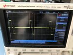
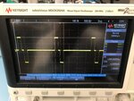
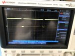
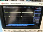
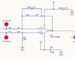
I want to generate a well balanced biphasic signal. The differential amplifier circuit has been attached. The resistors have the same precision (0.1%). The input voltage signals have the exactly same amplitude, but the output signal positive phase 1.9V, and the negative phase has 1.9875V. So why is there a difference?

Thank you,
 

Attachments

  • Differential Amplifier Qs.PNG
    Differential Amplifier Qs.PNG
    41 KB · Views: 175
  • Output Positive 1.9875.jpg
    Output Positive 1.9875.jpg
    1.8 MB · Views: 185
  • Output Positive 1.9V.jpg
    Output Positive 1.9V.jpg
    1.8 MB · Views: 183
  • Test Point 11.jpg
    Test Point 11.jpg
    1.8 MB · Views: 165
  • Test Point 9.jpg
    Test Point 9.jpg
    1.9 MB · Views: 173

Hi,

Please show the source and show the load.
Especially the impedances.

Klaus
 

Hi,

The source signals are in the Test_Point_11 and Test_Point_9 figures. Actually there is no load. The output of the differential amplifier goes to the voltage to current converter.
 

Whats the accuracy of the fdbk resistors ?

Here is a tool to get at error determination -


Regards, Dana.
 

I guess the sources ard 50 ohms? Amplifier input impedance is asymmetrical, 50k versus 150k. This explains part of the of gain asymmetry. You claim 0.125% asymmetry, I presume that's only an estimation.
 

50kOhms are connected to the inputs of the opamp inverting and non inverting pins. 100kOhms are connected as feedback resistor and connected to the ground.
 

Then do an end to end error analysis.

1) PSRR
2) Vos
3) AOL
4) R match
5) Differential input stage switch over*
6) CMRR

* RRIO have an input stage that has a non symmetrical input transition region
when changing from P channel to N channel input in the signal path. Some spec
sheets cover this, this one does not completely. You can see this effect in the graphs
Vos versus Vin.


Also are you making these high precision measurement with a scope ? What is its front end
accuracy ? Is it 8 bits ? Even with averaging its ENOB will not grow enough.


Regards, Dana.
 
Last edited:
50kOhms are connected to the inputs of the opamp inverting and non inverting pins. 100kOhms are connected as feedback resistor and connected to the ground.
Yes, I can read schematics. But you apparently didn't calculate the amplifier input impedances and the gain error caused by it.
 

Your scope, its datasheet, has conflicting info on the DVM, but
input to scope is 8 bit digitize, with averaging 12 bits. DVM probably
+/- 3 counts, so that in and of itself is quite a lot of error.

Again, a full end to end error analysis would be appropriate. And do a
high res external voltmeter to get accurate voltages.

What are your performance/error goals ?


Regards, Dana.
 

The opamp has fairly low open-loop gain at 2kHz. Maybe it also has fairly high even-harmonics distortion causing one phase amplitude to be squashed a little.
Maybe the 'scope has even-harmonics distortion?
 

The opamp has fairly low open-loop gain at 2kHz.
No, 3 MHz. The apparent amplitude asymmetry is unlikely caused by insufficient bandwidth.

A doubt that we can help to clarify the problem with the given information. According to the scope screenshot, you have about 1% asymmetry, more than can be explained by source and amplifier input impedance. Taking a cursor reading from the noisy trace seems however arbitrary, I would activate averaging and/or bandwidth reduction to see clear traces.

I tend to believe you have a real asymmetry in your circuit, however according MSO-X 2000 datasheet, the vertical accuracy isn't guaranteed better than 0.25 % of full scale or +/- 20 mV in your measurement.
 

The rail-to-rail opamp has poor symmetry, something like an ordinary transistor circuit has. An OPA134 audio opamp has distortion (gain= 1) that is 400 times less. Here is the poor symmetry (it is awful) of an ordinary transistor with no negative feedback:
 

Attachments

  • transistor distortion.png
    transistor distortion.png
    19.6 KB · Views: 153

The rail-to-rail opamp has poor symmetry, something like an ordinary transistor circuit has. An OPA134 audio opamp has distortion (gain= 1) that is 400 times less. Here is the poor symmetry (it is awful) of an ordinary transistor with no negative feedback
The comparison is flawed. Amplifiers like TLV2771 are surely not suggested for high end audio, but they easily achieve THD below 0.1 %. Unless there are hidden circuit elements connected (e.g. low impedance load, unexpected large source impedance), there's no reason why the post #1 circuit should expose the observed asymmetry.
 

Status
Not open for further replies.

Similar threads

Part and Inventory Search

Welcome to EDABoard.com

Sponsor

Back
Top