Continue to Site

Welcome to EDAboard.com

Welcome to our site! EDAboard.com is an international Electronics Discussion Forum focused on EDA software, circuits, schematics, books, theory, papers, asic, pld, 8051, DSP, Network, RF, Analog Design, PCB, Service Manuals... and a whole lot more! To participate you need to register. Registration is free. Click here to register now.

DHT22 or AM2302 or RHT03

Status
Not open for further replies.

bmandl

Full Member level 4
Full Member level 4
Joined
Feb 26, 2010
Messages
207
Helped
3
Reputation
6
Reaction score
3
Trophy points
1,298
Location
Slovenia
Activity points
2,966
Hello everyone!
Have anybody heard of this temperature and humidity sensor, which has three different names and uses some kind of 1-wire communication, which has nothing in common with Dallas 1-wire? I wanted to find some C code example for it (AVR or PIC), but all I can find is Arduino and C++ examples. I get to thinking, that this sensor is only usable with C++ language? I will try to write a C code for AVR or PIC microcontroller, but I don't understand a few things. I was thinking, if someone could explain this to me:
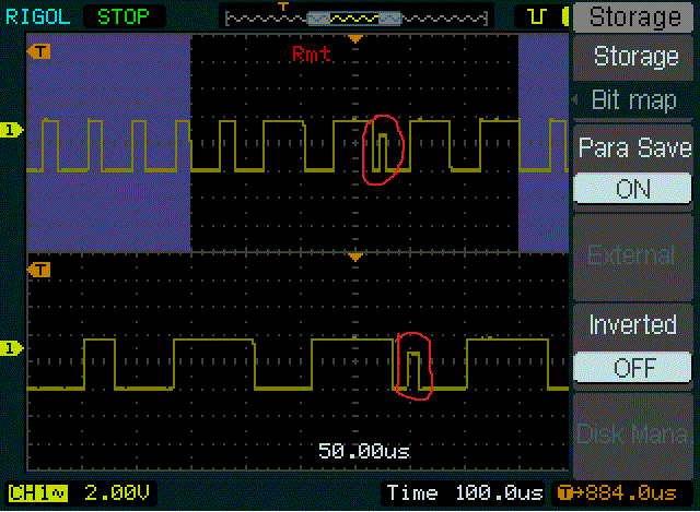
Datasheet, page 4: It says, that if sensor outputs positive signal for 26-28us, this means logic "0", but if it outputs positive signal for 70us, it means logic "1".
If this is so, I must measure time, for how long positive signal from sensor was present and then determine if it was "0" or "1"? Very strange way to separate two logic states is it not?
Ok, if someone could answer me to this questions please, I will be looking forward to start coding interface between sensor and microcontroller.
Regards!
 

Hi,

Have used the DTH11, the earlier version which has a poorer accuracy than the DHT22.

I programmed it in Pic Assembly and as you can see from comments fields of the attached code, they use custom timings for all their signals, not just the ones and zeros but the start pulses as well.

Expect there will be some C examples around, have you tried searching this forum ?
 

Attachments

  • dht11.rar
    925 bytes · Views: 116
  • Like
Reactions: bmandl

    bmandl

    Points: 2
    Helpful Answer Positive Rating
Thank you very much, this was very helpful for me. I will code everything in C, but I am waiting for sensor now (I've ordered it on ebay). Unfortunately, I didn't find anything on this forum with search string "DHT22" or "AM2302" or "RHT03". Google didn't find it neither, nothing else than Arduino and C++. But I will help my self with your assembly code and for that, thank you again.
EDIT: Pardon me, it looks like there is more results for DHT11 sensor. I found one MikroC example with PIC16F628.
 
Last edited:

Thank you very much, this was very helpful for me. I will code everything in C, but I am waiting for sensor now (I've ordered it on ebay). Unfortunately, I didn't find anything on this forum with search string "DHT22" or "AM2302" or "RHT03". Google didn't find it neither, nothing else than Arduino and C++. But I will help my self with your assembly code and for that, thank you again.

Hi,

Think you might have more luck if your search on DHT11; unless I am mistaken the protocol is virtually the same for the 11 and 22, its just the accuracy that different.

Found this manufacturers code snippet but no idea which C it is ?

Did you buy more than one sensor ? - I bought 2 of the DHT11 and there was a 5% difference in humidity reading between them, though the temps almost equal.
You can use the Salt Box method to check their humidity acccuracy.
 

Attachments

  • DHT22.doc
    32.5 KB · Views: 104

I ordered only 1 sensor. Yes, you're right, there is more results on DHT11. I also found some thread on AvrFreaks about it and everyone was complaining about accuracy of this sensor. AvrFreaks. How could it be, that it shows different RH's?
 

Hi,

I used this method to check my 2 DHT11s, one gave 80% the other 85% when they should have been 75%.
https://www.humidor-guide.com/humidor-preparation/calibrating-hygrometer

Think you have to consider two factors, first I expect the units are typically used in aircon and similar units where perhaps 5 or 10% difference is not really noticed.
Second, I often suspect many ebay / far east cheapies are maufacturers out of specification rejects, good enough to work but below their stated accuracy.

If you want good quality and accuracy it seems the SHT11 and similar Sensiron sensors work very well, if purchased though a major outlet like Farnells/ Digikey.
The problem is they are so expensive and as of course after all the trouble to get its custom serial link working I accidentally blew it !

I finally settle for the DHT11 to measure the approximate humidity as 10% out of specification made little difference in my application, and an NTC to give the accuracy needed for the temp control, replaced eventually by a DS18B20 sensor as some now supply them in a steel case with lead and connector already fitted.
 

I've made a RH and temperature meter with SHT75, but I got this sensor for free because this meter wasn't for me :). Now, I want to make one for myself, but this sensor is too expensive for me. It is true, that it is quality, but it is silly for amateur use, to give 30€ for one sensor, while you can get hole device for such money.
When I get the sensor and start coding, I will stop by again. Thank you for previous help.
 

Ok, I got the sensor, and I wrote basic routines for it. After I send a start signal to sensor, I get low signal response from it and then sensor pulls high, after that, it times out (for more than 80us). I don't know why. This asm, you sent me, it's not working, becouse It does not do the sequence as it is in datasheet (page 4).
Should I wait for more than 80us for sensor to switch state?

Hi,

Looking at the datasheets for the DTH11 and 22 they appear to be identical apart from the shorter opening pulse for the 22, though that makes no difference.

The code I sent is the dht11 core code that runs on my Pic 18F chips, the delay timings are based on a main oscillator of 4 mhz.

Have you used the data lines pull up resisitor ?

As to why its not working, as I have no idea what chip or complier your are using, let alone seeing the code you have produced its impossible for me to say. - I only know pic assembly.

If you use the info you have you should be able to work out the code sequence - as I had to - not easy but it can be done.

Some code here might help you.
http://www.sparkfun.com/products/10167

http://sheepdogguides.com/arduino/ar3ne1humDHT11.htm
 

I am using AVR GCC C compiler (C language). The code below is my function to send start signal and get response from DHT22 sensor:
Code:
uint8_t DHTStart(void)
{
	DHT_PORT_IZHOD;
	DHT_LOW;
	_delay_ms(25);
	DHT_HIGH;
	_delay_us(40);	
	DHT_PORT_VHOD;
	_delay_us(2);		
	/*Najprej pošlje pozitiven signal za določen čas, nato negativnega. Če med tem poteče timer, ni bilo odziva*/
	TCNT0 = 206;
	SREG |= _BV(7);
	while(!DATA_GET && !Timflag);
	if(Timflag){		
		SREG &= ~(_BV(7));
		Timflag = 0;
		return 0;
	}				//timeout po 80us negativnega signala
	
	TCNT0 = 206;
	while(DATA_GET && !Timflag);
	if(Timflag){
		SREG &= ~(_BV(7));
		Timflag = 0;
		return 0;
	}				//timeout po 80us pozitivnega signala
	
	return 1;			
}

Algorithm is like this:
MCU first send low signal to DHT data pin for 25ms and then high signal for 40us, then I set MCU pin to input and wait for DHT response. MCU is waiting for high signal from DHT for 90us (if this time is up, function returns "no response"), then MCU waits for low signal for 90us (if time is up->"no response"), then returns response. But I newer get response. I was debbuging my code with some LED blinking, to see where time gets up. DHT sent first high signal, but then it hangs on that - I got no low signal from it anymore. If I am not mistaken, I am doing exact algorithm as it writes in datasheet. I hope, you see any mistake.
Thank you.

- - - Updated - - -

I corrected it. I wrote it exactly like you did in your assembly, but still not working. No response.
 

I am starting to suspect, that sensor is fault.
 

Hi,

Well the dht11 sensor does work ok as you can see from my monitor.

Afraid I don't do C so cannot see any errors with your code, though I would do two things, reduce the opening host low pulse to 2ms as perhaps the sensor might not like such a long pulse of 25ms.

Also note that you need to give it 2 seconds before starting another read sequence; and you have got the 5k pull up ?

Do not know of any other way to test the sensor is good.
 

Attachments

  • ScreenShot001.jpg
    ScreenShot001.jpg
    24.5 KB · Views: 88

Hi:

Looking at exactly the same Thermometer/Sensor(RHT03) and saw your sample assembly code. I'm using an 18F458. What is the "D1" in your code for? Thanks.
 

It is register for 50us delay, that decrements every us (micro second).
 

Hi:

Looking at exactly the same Thermometer/Sensor(RHT03) and saw your sample assembly code. I'm using an 18F458. What is the "D1" in your code for? Thanks.


Here is a more complete subroutine which runs ok on my 4520 chip , so should work straight away on yours.
You just need to set up a port correctly and specifiy the User Registers needed like d1 at the begining of your code.
 

Attachments

  • dht11.rar
    2.2 KB · Views: 85

You are very generous to do this! Thank you! I will be testing this tomorrow after class and will let you know how it goes. I have it attached to the breadboard and would like to see what the results are in the registers! I saw something on MaxDetect that says the following is needed for conversion:

"DATA=16 bits RH data+16 bits Temperature data+8 bits check-sum
Example: MCU has received 40 bits data from RHT03 as
0000 0010 1000 1100 0000 0001 0101 1111 1110 1110
16 bits RH data 16 bits T data check sum
Here we convert 16 bits RH data from binary system to decimal system,
0000 0010 1000 1100 → 652
Binary system Decimal system
RH=652/10=65.2%RH
Here we convert 16 bits T data from binary system to decimal system,
0000 0001 0101 1111 → 351
Binary system Decimal system
T=351/10=35.1℃
When highest bit of temperature is 1, it means the temperature is below 0 degree Celsius.
Example: 1000 0000 0110 0101, T= minus 10.1℃
16 bits T data
Sum=0000 0010+1000 1100+0000 0001+0101 1111=1110 1110
Check-sum=the last 8 bits of Sum=1110 1110"


Hi,

The RH03/DHT11 datasheet shows the complete sequence of data collection.

That progam code does that, then takes the temp and hum binary values and uses the Ascii converter to produce ascii values suitable for a lcd or similar.

My code does not check for negative temps, something you could add if needed.

Please note that the delays used in that routine are based on a 4mhz oscillator, any other frequency and you will have to modify all the delay routines for it to work.
Also don't forget the 4.7k or 5K pull up resistor on the input pin.
 

Hi:

Thank you for the advice. I am using a 10mhz oscillator. I got the code to compile and run. I am having trouble(since I'm new with Assembly) to getting values from the device to the display. I had to divert attention to a Java project, which I just progressed on today. Now I can focus on this again for the weekend. I will update you with what I can get running. Thank you for your motivation, suggestions and sample code. I am using the "PIC Microcontroller and Embedded Systems" book from Mazidi, Mckinlay and Causey. More later.

Hi,

Don't know of that book, but its like any other, only as good as you can get on with it.

For more diy / practicable help perhaps look at these 2 sites.
They are modular so you can pick and choose what ever section you need.
Athough mainly geared to 16F chips it should be easy enough to mod for the 18Fs

http://www.winpicprog.co.uk/pic_tutorial.htm
**broken link removed**

You do not say what your display devices is ? if its a typical 16x2 lcd then you need to covert the hex results from the sensor to ascii .
Plenty of ready made converters here.
http://www.piclist.com/techref//index.htm

Again I have got some 18F lcd code examples if needed.
 

Hello!
It has been a long time, since I tried this sensor. Now, I managed to get it working, but only with DHT11. With DHT22 sensor, I am getting some kind of an disturbance signal while data aquisition. I happens always at the same time. And this causes, that checksum newer pass. I managed to record this error on oscilloscope, so that will be more clear. It is odd, that I get this with three different sensors. Does anyone has any idea, what can be wrong? I assume, that this is not software problem, because with DHT11 this newer happens.
 

Status
Not open for further replies.

Part and Inventory Search

Welcome to EDABoard.com

Sponsor

Back
Top