Continue to Site

Welcome to EDAboard.com

Welcome to our site! EDAboard.com is an international Electronics Discussion Forum focused on EDA software, circuits, schematics, books, theory, papers, asic, pld, 8051, DSP, Network, RF, Analog Design, PCB, Service Manuals... and a whole lot more! To participate you need to register. Registration is free. Click here to register now.

Develop a sensor with thermistor

Status
Not open for further replies.

lucasromeiro

Newbie level 5
Newbie level 5
Joined
Jun 15, 2010
Messages
9
Helped
0
Reputation
0
Reaction score
0
Trophy points
1,281
Activity points
1,365
Hello guys.

I'm using an efr32bg22 Bluetooth module and would like to read a thermistor with it!

I've never used a thermistor.

Reading a little about the subject, it seems a little complicated to me.
There are some formulas for obtaining a conversion but apparently the best way is to use a conversion table.

Unfortunately I don't know how to do any of them.

I would like to use the table or a method that helps to have greater precision.

I bought 2 thermistor models and I have them here with me:
NTCSP103JF103FT1S
TX06F103F3435ER

I had a temperature sensor that used a thermistor to measure the temperature inside a refrigerator. I want to do the same thing.

I disassembled the sensor and the circuit I found was as follows:
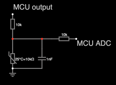
Captura-de-Tela-2022-12-17-a-s-11-30-01.png


I imagine that I can replicate this circuit, but the part of converting the ADC signal to the temperature accurately I still don't know how to do it.

Can someone help me?

Important: I intend to use the range from 30 to -40 degrees celcius.
Most of the time it will operate in the range of 10 to -20 degrees celcius (inside a fridge or freezer).

Can anyone help me with this?
 

Not sure what your problem is. If you use a table it’s pretty straightforward, you just have to do the math. For your voltage divider the output voltage MCU_ADC is Vref *Rth/(Rth+ 10K). From this you can calculate Rth for a given MCU_ADC. The manufacturer provides you a table of Rth vs temp; you just have to create a table for MCU_ADC vs temp. You also need to take into account the ADC conversion factor.

I question the use of that 10K resistor on the output; unless your ADC has a very high input impedacne, it’s going to contribute error.
Hello barry,
Thank you for your welcome!

I understood what you told me.

I would like a resolution of at least 0.1 degree celcius.

My SoC adc seems to have 12, 16, 18 and 20 bit options. Apparently it is more common to use the 16 bit. Perhaps we can use it as a reference.

As for the calculations, I know that there is an approximation that uses the Steinhart-Hart equation.

I didn't try to do a regression using datasheet points because in the places I researched people use this equation and not a polynomial regression. I don't know the reason for that...

I'm learning, I've never done anything with Thermistor.

But I'm still a little confused on the "best" way to do this.
For my use, the best way is the one that I can replicate for all my thermistors of the same model, without having to calibrate one by one and that gives me a resolution of at least 0.1 degrees calcius.

I found this material that talks a little about it and helps to calculate, but since I'm still a beginner, it left me confused.

https://learn.adafruit.com/thermistor/using-a-thermistor

there is an interesting table:
https://sparks.gogo.co.nz/ntc_thermistor.html

I have the thermistor datasheet:

https://www.ohmite.com/assets/docs/res_tx.pdf?r=false

https://product.tdk.com/system/file...og/tpd_automotive_ntc-thermistor_ntcsp_en.pdf
 

Hi,

don´t stress yourself.
A thermistor is nothing but a resistor. A variable resistor. So nothing special.

Your range is 70C and with a resolution of 0.1°C this just gives a ratio of 1:700 or less than 10 bits (output)
If you focus on the -20°C to +10°C it´s even better.

What I´d do:
* take the datasheet
* use Fig1 and draw in the vertical lines for your temperature range (limits)
* where these lines cross the thermistor line draw horizontal lines for the resistance (limits)
* draw a third horizontal line at the center of the horizontal lines. Use this value for your pull-up resistor connected to ADC_VREF. (to minimize errors)
* I also recommend to use excel to draw the "simulaton" of your circuit. To see the voltage range of the output and also to see about nonlinearities and errors. (0.3 x VRef ... 0.75 x VRef)

***
I agree with Barry regarding the output resistor. I´d omit it completely.
And I also question the 10nF capacitor. Depending on what you want to do .. but in most cases a 1uF won´t hurt, while it helps to suppress noise.

Klaus
 
Your range is 70C and with a resolution of 0.1°C this just gives a ratio of 1:700 or less than 10 bits (output)
If you focus on the -20°C to +10°C it´s even better.
Due to exponentional NTC characteristic, sensitivity varies strongly with temperature. You rather need 14 - 16 bit ADC for 0.1 K resolution. The other problem is that tolerance of most NTC is relative large compared to e.g. Pt100 sensors. Over wide range of 70 K you get hardly better accuracy than +/- 1K without individual sensor calibration.
 

Hi,

don´t stress yourself.
A thermistor is nothing but a resistor. A variable resistor. So nothing special.

Your range is 70C and with a resolution of 0.1°C this just gives a ratio of 1:700 or less than 10 bits (output)
If you focus on the -20°C to +10°C it´s even better.

What I´d do:
* take the datasheet
* use Fig1 and draw in the vertical lines for your temperature range (limits)
* where these lines cross the thermistor line draw horizontal lines for the resistance (limits)
* draw a third horizontal line at the center of the horizontal lines. Use this value for your pull-up resistor connected to ADC_VREF. (to minimize errors)
* I also recommend to use excel to draw the "simulaton" of your circuit. To see the voltage range of the output and also to see about nonlinearities and errors. (0.3 x VRef ... 0.75 x VRef)

***
I agree with Barry regarding the output resistor. I´d omit it completely.
And I also question the 10nF capacitor. Depending on what you want to do .. but in most cases a 1uF won´t hurt, while it helps to suppress noise.

Klaus
Hi klaus,
Thanks for your response!

My application requires super low power consumption.
Thanks for the tip on better choosing the resistor value of the resistive divider, I hadn't thought of that. That line idea was great.
Now I have a doubt in mind.
My SoC will run on 2 AA batteries, it runs from 3.3v up to 1.7v.
So the input voltage of my resistive divider will change.
But since my ADC reference voltage will also change with it, will that be a problem?

I also have to think about the useful range of the ADC measurement, to optimize it somehow.

I'm going to do a simulation in excel to study this!

Looking at the datasheet of one of the thermistors, I noticed that one of them is much more linear than most thermistors. there are some interesting formulas that maybe I can use! I found this interesting, maybe it can help me in some way.

But the other model has a table with temperature values, which also helps, I'm still thinking about which of the 2 would be better to use.

see:

Model 1
1671319943251.png

1671319992984.png

1671320027524.png


Model 2:
1671320053316.png
 

Hi,

FvM is right about ADC resolution. Your ADC needs more than the 10bit (output) resolution.
You also need to take care about the used input range, which is just 0.45 x FS.
16 bit should be sufficient.

0.1°C resolution is no problem.
0.1°C accuracy is not likely to achieve with theses thermistors.

Power consumption:
You need to give a value for the expected consumption for us to give good advice.
And you need to give how often you need a temperature value (per second, minute...)

If VRef is not constant then you need "ratiometric" measurement method. Means it's very important that pull up resistor is connected to VRef...
... and that both (measurement value as well as VRef) need identical time constant (cutoff frequency).

Klaus
Hi Klaus,

I didn't quite understand what I said (0.45 x FS). Can you explain better?


As for accuracy, what accuracy do you think we will achieve?


Energy consumption should be as low as possible, I don't have a target value.

My measurement will be once a minute.


VRef is not constant, but the VRef will be the same value as my digital output that would feed the resistor divider, correct? could thus turn it on only at the time of reading.


I'm not familiar with the term "ratiometric".
 

Hi,
I didn't quite understand what I said (0.45 x FS). Can you explain better?
if you just use a resistor and thermistor in series you output voltage is: about 0.3 x V_in ... 0.75 x Vin.
Now if V_in = VRef, then also the digital output code is just 0.3 ... 0.75 x FullScale. This is the measurement range.
It"s just 0.45 (or 45%) of FullScale.

Accuracy: I won't do the error calculations for you. But I see the thermistor is rated with 1% error in initial value and 1% error in B.
Then I don't know the tolerance and drift of your resistor,
Nor do I know the errors of the ADC.
Also - if you use a capacitor - you need to wait: from applying supply to starting conversion. The longer you wait the less the error.
I do these calculations usually before thinking about the circuit. Often with use of Excel.

Energy consumption should be as low as possible, I don't have a target value.
this is the answer I wanted to avoid.
If you take it not seriously .. it is meaningless, because every developer has his own definition of "low as possible"
If you take it seriously, then developing becomes a never ending story: one says 100uA, the next says 80uA, the next says 70uA,
Then 69uA, then 68.5uA, then 68.4uA, then 68.39uA ...
Improvements microamperese, nanoamperes, picoameres ... when do you stop "as low as possible" since each one is "lower than the one before".
Also you can't type in "as low as posssible in your calculator".
Especially when you work in a team (forum) you have to give a value. Maybe two: one "absolute maximum" and one "nice to have"

Once a minute: then you may switch OFF the measurement current (I'd use a P-CH Mosfet), this helps to reduce current consumption.
Let's say it os ON for 1 second in one minute ... means the average current is about 1/60 (ignoring the capacitor charging current)
Let's say from 2.5V/ 60k = 42uA down to below 1uA average.
You need to: Switch ON measurement supply --> wait about 10 tau for the capacitor to charge to less than 1LSB error --> do the conversion(s) --> switch OFF measurement supply --> sleep for 1 minute

Do an internet search for "ratiometric measurement" and look for circuits and benefits.
Then ask if you need to know details.

Klaus
--- Updated ---

Added:
Did you consider a digital temperature sensor? I2C one?
It may be easier in hardware and software ... and you can choose according accuracy and resolution.
 
Last edited:
Hi,
if you just use a resistor and thermistor in series you output voltage is: about 0.3 x V_in ... 0.75 x Vin.
Now if V_in = VRef, then also the digital output code is just 0.3 ... 0.75 x FullScale. This is the measurement range.
It"s just 0.45 (or 45%) of FullScale.

Accuracy: I won't do the error calculations for you. But I see the thermistor is rated with 1% error in initial value and 1% error in B.
Then I don't know the tolerance and drift of your resistor,
Nor do I know the errors of the ADC.
Also - if you use a capacitor - you need to wait: from applying supply to starting conversion. The longer you wait the less the error.
I do these calculations usually before thinking about the circuit. Often with use of Excel.

this is the answer I wanted to avoid.
If you take it not seriously .. it is meaningless, because every developer has his own definition of "low as possible"
If you take it seriously, then developing becomes a never ending story: one says 100uA, the next says 80uA, the next says 70uA,
Then 69uA, then 68.5uA, then 68.4uA, then 68.39uA ...
Improvements microamperese, nanoamperes, picoameres ... when do you stop "as low as possible" since each one is "lower than the one before".
Also you can't type in "as low as posssible in your calculator".
Especially when you work in a team (forum) you have to give a value. Maybe two: one "absolute maximum" and one "nice to have"

Once a minute: then you may switch OFF the measurement current (I'd use a P-CH Mosfet), this helps to reduce current consumption.
Let's say it os ON for 1 second in one minute ... means the average current is about 1/60 (ignoring the capacitor charging current)
Let's say from 2.5V/ 60k = 42uA down to below 1uA average.
You need to: Switch ON measurement supply --> wait about 10 tau for the capacitor to charge to less than 1LSB error --> do the conversion(s) --> switch OFF measurement supply --> sleep for 1 minute

Do an internet search for "ratiometric measurement" and look for circuits and benefits.
Then ask if you need to know details.

Klaus
--- Updated ---

Added:
Did you consider a digital temperature sensor? I2C one?
It may be easier in hardware and software ... and you can choose according accuracy and resolution.
Hi Klaus,


Thanks for the answers, they help me to grow.


As for the energy cost for the thermistor, something around 10uA or less would be acceptable for my application.


I still don't understand the difference between using a mosfet and using a gpio to feed the resistive divider...


As for your question about using a digital sensor:

Yes, I thought about it.

I looked for a sensor that has a power supply range between 1.7 and 3.3v, with an energy consumption similar to what I mentioned above and with an accuracy of at least 0.5 degrees C. I didn't find good cost/benefit options.... A good one target cost for me is something less than 1 dollar for this sensor.


In my searches I found the following options:

aht-15 (3u$)

TMP112AIDRLR (1.6u$)

I need something cheaper if possible.


Do you know of any CI options that would fit well with this solution?
 

Using a GPIO will not give you the accuracy you need; the output voltage is pretty much undefined. e.g. it could be anywhere between 2.4 and 3.3 V for a TTL output.

If you’re expecting to consume only 10uA, then you’re going to need some amplification, as your maximum voltage will be 0.1V.
 
Using a GPIO will not give you the accuracy you need; the output voltage is pretty much undefined. e.g. it could be anywhere between 2.4 and 3.3 V for a TTL output.

If you’re expecting to consume only 10uA, then you’re going to need some amplification, as your maximum voltage will be 0.1V.
I didn't understand how my maximum voltage will be 0.1v
--- Updated ---

Others CI's:

TMP112AIDRLR
TMP126NDCKR
SHTC3
AHT-15
BME-280
 
Last edited:

Using a GPIO will not give you the accuracy you need; the output voltage is pretty much undefined. e.g. it could be anywhere between 2.4 and 3.3 V for a TTL output.
Don't agree. GPIO are effectively CMOS switches to VDD/VSS with 30 - 100 ohm resistance. Internal supply rail voltage drops are probably causing the largest error.

Regarding sensor power consumption, I would expect operation with low duty cycle. Average current consumption counts, 10 uA average can be achieved with any of the quoted sensor solutions, even with higher current consuming Pt1000.
 
Hi,

How do yo do a search for temperature sensors?
I went to a distributor site and used the search function.
Farnell gives AS6212 for example.

Klaus
 
Hi,

How do yo do a search for temperature sensors?
I went to a distributor site and used the search function.
Farnell gives AS6212 for example.

Klaus
Hi Klaus,
Normally I use the digikey website.
What you said is more complete?
The Ci you quoted me has great features, but the solder pad is too complex for my team to solder this package.
The ones I mentioned are simpler.
 

If you really want to use a thermistor, then consider this.

Actually, unless what you call MCU Output is adequately accurate and stable, then you cannot rely on your circuit for accurate measurement. Usually, because of variations in "MCU Output", you want to measure the voltage across the 10K resistor to determine the current. Then you quickly measure the voltage across the thermistor to calculate the its resistance.

Your circuit cannot achieve that.
 
Last edited:
This SOC is not your SOC but ap note presents some interesting calculations and methods
to achieve high res -


This SOC looks like -

View attachment 180276

Multiple copies of above resources in many cases onboard.


Regards, Dana.
Thanks!
I will read the document and soak up the knowledge!
I am very afraid that using a thermistor will be laborious, not accurate and expensive if I want to improve the accuracy within 0.5 degrees...

I'm still evaluating everything as possible.

The combination of thermistor errors makes me very concerned about the quality...Accuracy.
 

I didn't understand how my maximum voltage will be 0.1v
--- Updated ---

Others CI's:

TMP112AIDRLR
TMP126NDCKR
SHTC3
AHT-15
BME-280
I was wrong, it’s 0.01V. But that’s assuming continuous operation, not low duty cycle.

10uA * 10K (thermistor) = 0.01
 
Hi,

The value of your thermistor is not 10k.
Since it's a temperature measurement device it depends on temperature. Thus it has a "range" you need to calculate with:
The range is about 7k ... 200k.

Thus the voltage at a 10uA constant current source is
70mV ... 2V
--> now you see it can't work on a 1.7V supply

*****
Digital sensor:
* as said: the AS6212 is just one example ... of several

Package size:
Thus you should do the search on your own, because we don't know all your requirements.

Klaus
 
Last edited:
Status
Not open for further replies.

Similar threads

Part and Inventory Search

Welcome to EDABoard.com

Sponsor

Back
Top