Continue to Site

Welcome to EDAboard.com

Welcome to our site! EDAboard.com is an international Electronics Discussion Forum focused on EDA software, circuits, schematics, books, theory, papers, asic, pld, 8051, DSP, Network, RF, Analog Design, PCB, Service Manuals... and a whole lot more! To participate you need to register. Registration is free. Click here to register now.

Designing LPF for 30MHz

Status
Not open for further replies.

neazoi

Advanced Member level 6
Joined
Jan 5, 2008
Messages
4,157
Helped
13
Reputation
26
Reaction score
15
Trophy points
1,318
Location
Greece
www.microwave.gr
Activity points
37,199
Hello, I would like to build a LPF for 30MHz cut-off using LC.
Power input will be something like 1W or so.
Output impedance must be 50R.
The input will be fed from an amplifier that has a choke in series with the PSU to the BJT collector, and a 100nF capacitor from the collector to the output. I do not know the impedance of such a thing. If I knew that I could try something with the RFsim99.

I would like some help or any schematics/simulations if possible.
 

So You don't have any matching circuit between filter and output stage.
A filter can easily be designed for 50:50 Impedances but you loose power because of this mismatch at this level of power..
The designer has to know output impedance of the final stage, otherwise it won't work..
 
  • Like
Reactions: neazoi

    neazoi

    Points: 2
    Helpful Answer Positive Rating
So You don't have any matching circuit between filter and output stage.
A filter can easily be designed for 50:50 Impedances but you loose power because of this mismatch at this level of power..
The designer has to know output impedance of the final stage, otherwise it won't work..

It is difficult for me to calculate the output impedance of the amplifier.
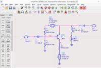
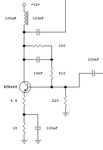
Here the schematic of the amplifier I use. How can I calculate the output impedance?

All my measurements are done at 50R but this is definitely not a 50R output.
 

Attachments

  • Untitled.png
    Untitled.png
    10.7 KB · Views: 119

By working of the feedback structure, the output impedance will depend on the connected generator impedance. And asking for the output impedance (a small signal quantity) is probably not the right question. You rather want to know the load impedance that achieves maximum undistorted output power, provided the generator input power is variable.

A match box is the best tool to find out the useable output impedance.
 
  • Like
Reactions: neazoi

    neazoi

    Points: 2
    Helpful Answer Positive Rating
By working of the feedback structure, the output impedance will depend on the connected generator impedance. And asking for the output impedance (a small signal quantity) is probably not the right question. You rather want to know the load impedance that achieves maximum undistorted output power, provided the generator input power is variable.

A match box is the best tool to find out the useable output impedance.

If I understood correctly, the input signal level to this amplifier is adjustable, and all my measurements (harmonics, distortion, power) have been done using a 50R load (the 50R input of the scope).

1. Is what I have done enough? I.e. is it good to assume it to be 50R "suitable" even though the system may be not matched to 50R, just because it has the desired characteristics at 50R? (low distortion and desired output power).

To explain this and make it more clear to you, why should I bother actually matching it to 50R, if an unmatched circuit gives the desired characteristics when measured at 50R?

However, if I try to measure at the 1M scope input the VPP levels rise much (as expected).

2. In another buffered oscillator I have, which is known to be matched close to 50R, the VPP levels do not change too much when measuring at 50R and at 1M scope inputs. What does that mean, compared to the previous amplifier?
 

1. Is what I have done enough?
Depends on what you want to achieve. To get maximal power out of the amplifier, use a matching circuit. I suggested to find the matching empirically. Wideband (e.g. 1 to 30 MHz) matching will be only achieved with a transformer.
What does that mean, compared to the previous amplifier?
It means that the present amplifier's output impedance is higer than 50 ohms, as expectable.
 

Depends on what you want to achieve. To get maximal power out of the amplifier, use a matching circuit. I suggested to find the matching empirically. Wideband (e.g. 1 to 30 MHz) matching will be only achieved with a transformer.

It means that the present amplifier's output impedance is higer than 50 ohms, as expectable.

Thanks for the answer it is clear to me now!

This gives me an idea, if a system is matched exactly to 50R, it should measure the same VPP value at both 50R and 1M on the scope, shouldn't it?

So there is nothing to worry, it is just you are loosing power with improper matching, but otherwise it is ok as long as your measurements are done in a specific load and the system is designed for that load.
A note, trying to bring the impedance down using a step down transformer would bring the voltage down as well, just a note. Also I do not think all HF antennas have 50R impedances, else why would an antenna tuner needed...

The only reason I could think for this specific system to be altered to have well defined output impedance, is to be able to design the output filter asked in post #1. The question remains...
 

Connecting a high impedance load to a 50 ohm source will still give you double output voltage compared to 50 ohm load operation.

The radio amateurs among Edaboard members will know better, but I think the need for impedance matching in the short wave band is also imposed by the antennas which have rarely 50 ohms impedance.
 
  • Like
Reactions: neazoi

    neazoi

    Points: 2
    Helpful Answer Positive Rating
Hello, I would like to build a LPF for 30MHz cut-off using LC.
Power input will be something like 1W or so.
Output impedance must be 50R.
The input will be fed from an amplifier that has a choke in series with the PSU to the BJT collector, and a 100nF capacitor from the collector to the output. I do not know the impedance of such a thing. If I knew that I could try something with the RFsim99.

I would like some help or any schematics/simulations if possible.
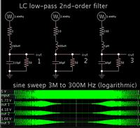
Here are my simulations of a 30MHz second-order low-pass filter.

Your 100 nF cap is very high compared to those in the filter. It is unlikely to have much effect on your signal.

Three variations show the effect of different input impedances.


Notice the rolloff curve is steeper when the input resistance is low.
 
  • Like
Reactions: neazoi

    neazoi

    Points: 2
    Helpful Answer Positive Rating
It is difficult for me to calculate the output impedance of the amplifier.
Here the schematic of the amplifier I use. How can I calculate the output impedance?

(Edit..sorry distraction error and time constrain, for not finishing corrections in bold)
All my measurements are done at 50R but this is definitely not a 50R output.
Zo is simply the unbypassed Rc or 510 +Rbe' Divided by the Av feedback ratio.

Av is the gain or ratio of the unbypassed collector to emitter impedance,

Perhaps you wish to change match 60 ohm output impedance to free space impedance or stepup with RF transformer, whatever works best.


Whereas the DC gain for bias current to achieve higher gain but not overheat the device with >20% power loss in class A is limited by the total resistance Rc/Re and reference, to Vbe.
 
  • Like
Reactions: neazoi

    neazoi

    Points: 2
    Helpful Answer Positive Rating
From Harmonic Balance simulation, I get an output impedance of ~60 Ohm for this amplifier at 30 MHz. Not too bad, the difference from 50 Ohm doesn't cause too much problem in filter synthesis.


For the low pass filter calculation, you can use Nuhertz Filter Free (limited but free):
**broken link removed**

or other simpler synthesis like this:
**broken link removed**

- - - Updated - - -

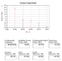
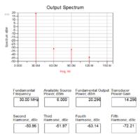
Output spectrum at 30MHz with 10mW input power, without low pass filter:


These are good news! I did not expect the output impedance to be that close to 50R.D
oes it depend too much on the transistor type? For example what if I use 2N4401?
I think I am going to better use one of these programs **broken link removed** or rfsim99 they seem easier to me.

My measurements on the FFT show a much less amount of harmonics without an LPF out of this amplifier though
 

Ensure Vce min is >2 for symmetry , as this is where hfe is low and current is high near saturation and increase V+ as required for Pout with low THD, then use autotransformer or tapped coil out for voltage gain to match free space higher impedance on antenna.
 
  • Like
Reactions: neazoi

    neazoi

    Points: 2
    Helpful Answer Positive Rating
Does it depend too much on the transistor type? For example what if I use 2N4401?

Ok, I spent 10 more minutes to find the model for that transistor and try it. If you just replace the transistor without tweaking the circuit (feedback), it works very poorly. Frequency response is really bad, gain drops from 13dB @ 10MHz to 9dB @ 30MHz.

My measurements on the FFT show a much less amount of harmonics without an LPF out of this amplifier though
Of course, it changes a lot with input power. My plot above is for 10mW in, 200mW out. And maybe your scope with the FFT function is adding some low pass filtering itself, because it has limited input bandwidth.

I think I am going to better use one of these programs **broken link removed** or rfsim99 they seem easier to me.

I can't comment which of the free simulators is best. We have other RF simulators (Keysight ADS, AWR Microwave Office) here and I have no experience with the free circuit simulators.

For filter synthesis (different topic than circuit simulation) I recommend Nuhertz if you want to have control over the filter details (expert level). For a beginner, it might be overwhelming, but it is really powerful.

- - - Updated - - -

Frequency response is really bad, gain drops from 13dB @ 10MHz to 9dB @ 30MHz.

However, for harmonics the circuit performs better with 2N4401, maybe because the feedback is wrong (too much negative feeedback)

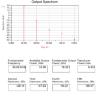
Spectrum with 10mW @ 30MHz input power, 80mW out

 
Last edited:
  • Like
Reactions: neazoi

    neazoi

    Points: 2
    Helpful Answer Positive Rating
I have found that too in another more powerful amplifier I designed once upon a time.
Multiple paralleled 2n4401 gave much better harmonic response than a single 2sc2166 designed for the purpose. Both were operating in deep class-A and very inefficient. The multiple 2n4401 needed a blower just above them (only about 7% efficient)

- - - Updated - - -

Ensure Vce min is >2 for symmetry , as this is where hfe is low and current is high near saturation and increase V+ as required for Pout with low THD, then use autotransformer or tapped coil out for voltage gain to match free space higher impedance on antenna.

Thanks a lot!
 

The better harmonics is just because the amplifier has less gain @ 30MHz with the 2N4401, and Pout=80mW at Pin=10mW (compared to Pout=200mW at Pin=10mW for the BFR96).

Here is a more fair comparison, with BFR96 running at Pin=5mW, Pout=100mW:

 
  • Like
Reactions: neazoi

    neazoi

    Points: 2
    Helpful Answer Positive Rating
BFR96S cannot provide 1W output power@30MHz regarding to my past experiences.
Input impedance of the filter will-at the same time-load of the PA so a good approximation for Optimum Load value from Load Line Theory ( for Class-A PAs)

Ropt=Vdc/Idc

So, if the input impedance of the filter is designed in according with this value ( of course output impedance can be 50 Ohm) desired power level can be catched by some tweaks.
 
  • Like
Reactions: neazoi

    neazoi

    Points: 2
    Helpful Answer Positive Rating
Start with specs..


Any questions? State all requirements explicitly.


Once defined any final config can be tuned for any Pout , Zout, Zin, THD, 3IP, Av , Vcc, F range, SNR, but these are minimum parameters to define component ratios and or values. Others may include Idc max.


then. selection of good tranny rated for at least 2x power you want out and 5x the transition frequency in the case size and cost to match. Unless doing microwave...

https://www.digikey.com/product-sea...=1&stock=1&quantity=0&ptm=0&fid=0&pageSize=25


For low voltage high current, choose low Vsat for better THD, otherwise ensure Vce.min = 2V !! With full swing.


e.g. https://www.digikey.com/product-detail/en/ZTX653/ZTX653-ND/92504

Then choose input and output impedance and use negative feedback gain to reduce Rc output impedance, then consider bootstrap bias from emitter R divider positive feedback to base to raise input impedance lowered by negative feedback gain. Then you choose resonant circuit to provide additional gain and impedance matching if 1 freq. or if not use coil on collector for 2x swing wideband output. DC negative feedback stabilizes DC Q point and un-bypassed Rc'/Re' ratio determines AC gain. Analyzing all R ratios determines stability for Q point and AC gain. Calc RC for breakpoints.
 
  • Like
Reactions: neazoi

    neazoi

    Points: 2
    Helpful Answer Positive Rating
Status
Not open for further replies.

Part and Inventory Search

Welcome to EDABoard.com

Sponsor

Back
Top