Continue to Site

Welcome to EDAboard.com

Welcome to our site! EDAboard.com is an international Electronics Discussion Forum focused on EDA software, circuits, schematics, books, theory, papers, asic, pld, 8051, DSP, Network, RF, Analog Design, PCB, Service Manuals... and a whole lot more! To participate you need to register. Registration is free. Click here to register now.

delay circuit project

Status
Not open for further replies.

Ghost69

Newbie level 4
Newbie level 4
Joined
Jun 25, 2013
Messages
7
Helped
0
Reputation
0
Reaction score
0
Trophy points
1
Activity points
50
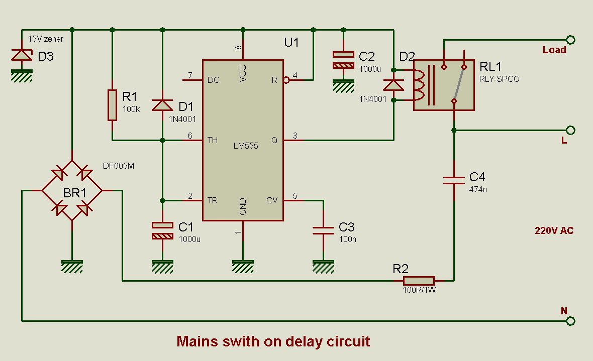
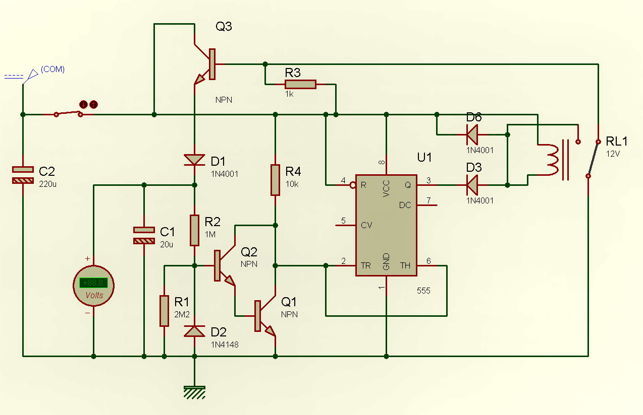
i am trying to make a delay circuit which gives a delay of 4 minutes,during which the
supply is disconnected from the output.The delay must start once power is cut off from the circuit,and even if power is back before 4 minutes the power must be cut off from the output till the 4 minutes are over.all the components must be powered by the input source.please do help..
 

use 555 ic based timer circuit .a lot of circuits are available
 

You mean If the main power not present.... the circuit (which gives the delay of 4 minutes) is powered by battery....
 

i already solved it using a 555 timer powered by a battery and a relay to the output.but the project coordinator has now specified that a battery cannot be used for powering the delay circuit.
 

i already solved it using a 555 timer powered by a battery and a relay to the output.but the project coordinator has now specified that a battery cannot be used for powering the delay circuit.

How about to use the CMOS 555 Timer (LMC555) instate and use a big capacitor instate a battery ?
 

How about to use the CMOS 555 Timer (LMC555) instate and use a big capacitor instate a battery ?

what is the difference between LM555 and LMC555?
why can't the capacitor be used in case of a LM555?
 

Good day
the differences between the LM555 and LMC555 are many in terms of nature (BJT/CMOS) , operating voltage range , max working frequency etc , but the main difference that concern the suggestion of the capacitor is the power dissipation and supply current : for the LMC555 , the supply current at 5V DC is typically 100 micro amps , while it is about 3 milli amps for the LM555, i think Pico suggested using a bank of Capacitors say like 10000 micro F with a resistor in series to supply the LMC555 from while the power is off , however i dunno if this is possible or fits to your application
hope this was helpful
regards
 

It is very common circuit application used for protecting fridge or AC compressors. It is powered by mains. When mains is switched on, a electrolytic capacitor starts charging. This is timing capacitor for LM555 timer IC. After required time has passed, the capacitor is charged to enough level that 555 IC now changes state at its ouput, which is connected to a relay and this turns on the load. When mains power is switched off, relay is deactivated, the capacitor is discharged rapidlly through a diode. Now it is ready for another delay, when power restores.
 

so any idea how to trigger the 555 IC once the mains power goes out n not be triggered again during the delay period even if power is back online?
 

basically a 555 monostable circuit respond to a falling edge as trigger , the rising edge has no effect on trigging

- - - Updated - - -

if you could manage to use the mains going off to generate a falling edge , this may work
 

basically a 555 monostable circuit respond to a falling edge as trigger , the rising edge has no effect on trigging

- - - Updated - - -

if you could manage to use the mains going off to generate a falling edge , this may work

so basically i should connect the dc supply terminal to pin 2 of the IC?
 

Impimenting fixed time delay everytime when mains is restored is easy like in this schematic. R1, the timing resistor can be upto 2M2 ohm for longer periods.


But the rquirment as in post #1 can be acheived. It is better becuse it will minus the time when mains is off from the four minutes and give a delay of remaining time. If mains is off for more than four minuites then there will be no delay thus improving efficiency.
It still uses a capacitor which was fully charges when mains was present. When mains is off it is slowly discharged to a certain level in four minutes. When mains restores, circuit stars monitoring voltage on it. When voltage drops to pre dtermined level, output is enabled and capacitor is charged to the full potential also.
 

The shown circuit provides power-up delay with a not so well-defined discharge behaviour for short power drops. But as shown, it can't achieve the specified 4 minutes minimal power-off, I think.
 

Yes it take few seconds to discharge through relay and circuit. Timing capacitor and filter capacitor values can be as low as 100uF for further speedy discharge. A fridge compressor can withstand a short period a very small power break.

With updatd values,
 
Yes it take few seconds to discharge through relay and circuit. Timing capacitor and filter capacitor values can be as low as 100uF for further speedy discharge. A fridge compressor can withstand a short period a very small power break.

With updatd values,

thanks for the circuit..is there a detailed explanation for the above circuit?
 

Basically it consists of two sections. Power supply and scimitt trigger around 555 timer IC driving output relay.
https://electronicsclub.info/555timer.htm
555 inverting buffer circuit
(a NOT gate)


NOT gate symbol
The buffer circuit's input has a very high impedance (about 1M) so it requires only a few µA, but the output can sink or source up to 200mA. This enables a high impedance signal source (such as an LDR) to switch a low impedance output transducer (such as a lamp).
It is an inverting buffer or NOT gate because the output logic state (low/high) is the inverse of the input state:

Input low (< 1/3 Vs) makes output high, +Vs
Input high (> 2/3 Vs) makes output low, 0V
When the input voltage is between 1/3 and 2/3 Vs the output remains in its present state. This intermediate input region is a deadspace where there is no response, a property called hysteresis, it is like backlash in a mechanical linkage. This type of circuit is called a Schmitt trigger.
If high sensitivity is required the hysteresis is a problem, but in many circuits it is a helpful property. It gives the input a high immunity to noise because once the circuit output has switched high or low the input must change back by at least 1/3 Vs to make the output switch back.


When power is applied, first timing capacior is in discharged state and relay is in off position. The capacitor is slowly chargs in 4 minuits.When its voltage exceeds 2/3V of supply voltage, output at pin #3 activates the relay and load is on. When mains does off, supply of circuit also tuned off. The filter capacitor and timing capacitor are discharged quickly through relay and circuit. The circuit waits for mains to turn on to deliver another delay before turning on the load( althogh power to the circuit is off).
 

Relay is initially off. After delay time is elapsed, it is turned on. When power goes , there is no power to circuit or relay. It cannot remain in on position. It remain in this condition when power is applied again. After power turns on, the relay remains in off position for another delay time. C1 ,Ri are timing network. C2 is filter capacitor for power supply. C is ripple filter and C4 is used to convert 220V to 12V.

For fast swithing off response as pointed out by FvM, here is another version with a few additional cmponents.

Here the timing capacitor is discharged very rapidly.


Trace showes when mains voltages are gone, darlington pair is trigged withen two or three cycles and discharges timing capacitor as shown in lower trace. It also help for more precise timing.

A big risk is that all parts are connected to mains so a there is a big risk to lethal elctrical shock which may kill. Put a 470K resistor across C4 as it is charged to full potential and it can cause a svere shock even after circuit is disconnected from mains.
**broken link removed**
 
how can i time the 555 unit for when the capacitor is discharging instead of when it is charging?
 

This circuit works as desired.
Switch cuts power to the circuit simulating mains is turned off. Relay is imedeately turned off. It does not matter how many times mains is turned off/on until delay time is passed. Then relay is activated. Other contacts of relay controles load which are not shown. Supply can be transformerless as before or a small tansformer can be used which also provide isolation from mains.


Status
Not open for further replies.

Part and Inventory Search

Welcome to EDABoard.com

Sponsor

Back
Top